ø 14
M8
M6
(1)
(1) (2) (3)
M4 UNI5721
Pag.
6 - Manual code:
119D U 64 ver.
3 05/2013 © CAME cancelli automatici s.p.a. - The data and information reported in this installation manual are susceptible to change at any time and without obligation on CAME cancelli automatici s.p.a. to notify users.
ENGLISH
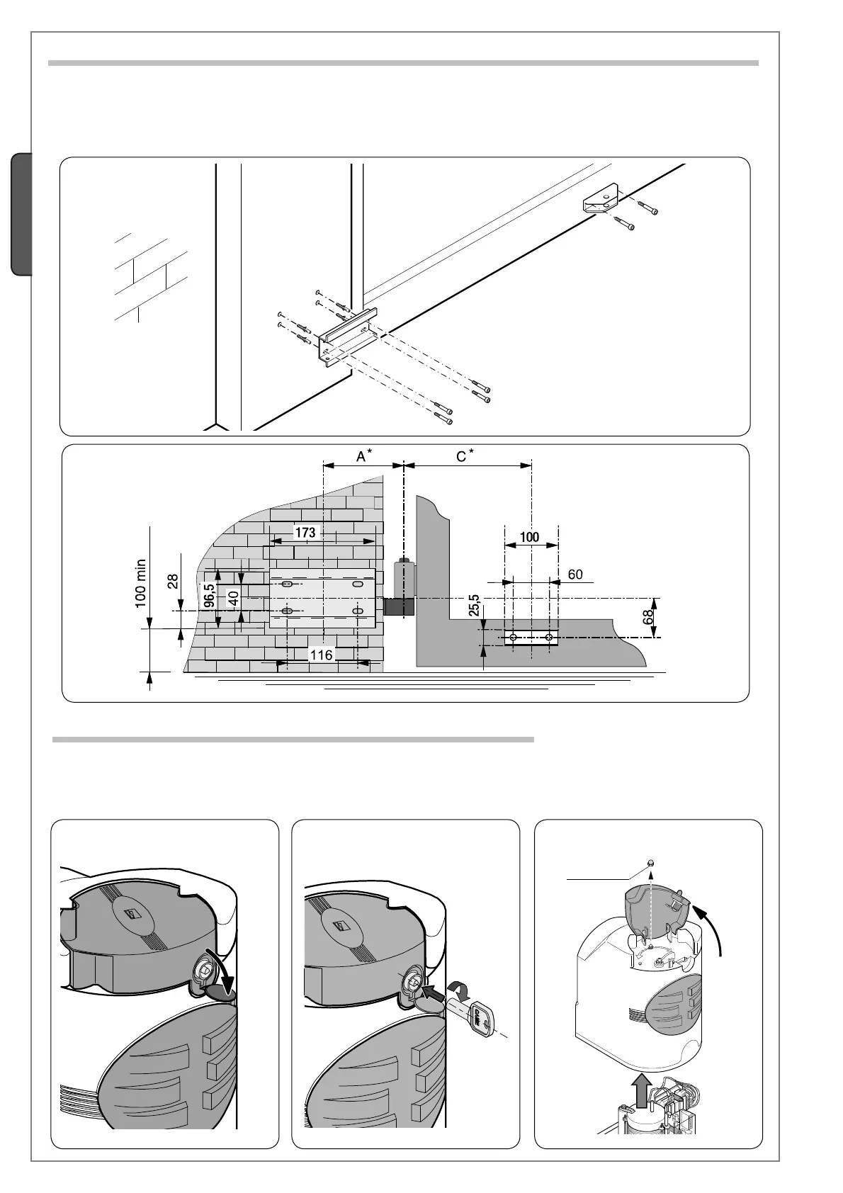
5.5 Applying the pillar bracket and A gate bracket
- Secure the pillar bracket to the pillar using M8 screws and ø14 mould inserts making sure the minimum distance of 100 mm
from the ground is met.
- Fix gate bracket “A” (with M6 screws or by welding) to the gate leaf making sure the measurements mentioned in the table on
page 2 and the 68 mm uneveness between the two brackets are met.
Pillar bracket
Gate bracket “A”
* See “Basic measure”, p. 3
Open the lock cover (1).
Insert the key, push it down and turn it clockwise (2).
Lift the cover, loosen the M4 hex nut and remove the cover from the gearmotor assembly (3).
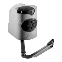
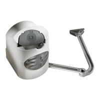
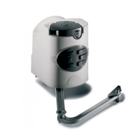
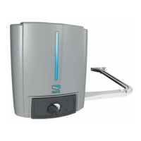
5.6 Installing the gearmotor
 Loading...