EasyManuals Logo

CAME Ferni Series User Manual

CAME Ferni Series
36 pages
To Next Page IconTo Next Page
To Previous Page IconTo Previous Page
Page #7 background imageLoading...
Page #7 background image
2.1 - Fitting the Control Panel in the Casing
STAGE 2 - WIRING & ELECTRICAL
6
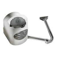
Securely fasten the control panel PCB to the
casing with the screws supplied.
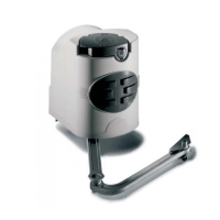
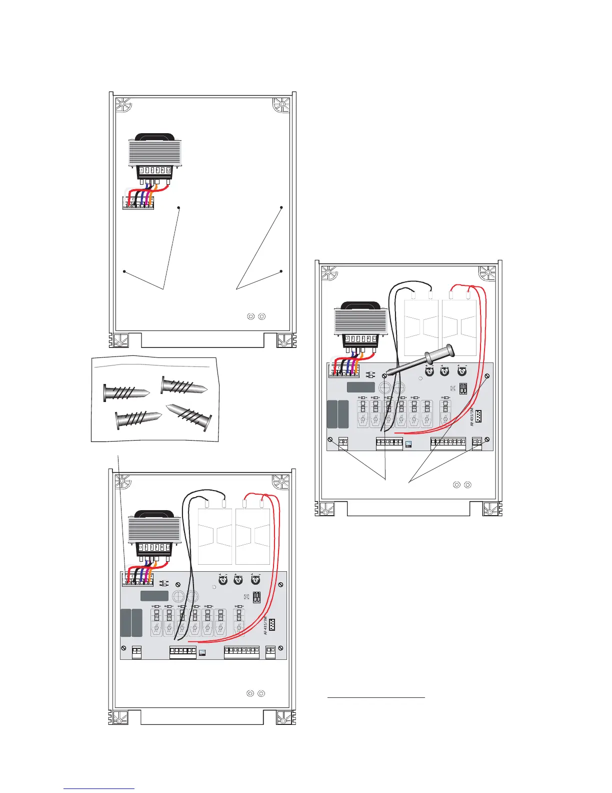
Plug the green connector from the transformer to
the PCB ensuring that it connects the correct way.
NB FROG Series Motors:
connect the black wires
coming out of the board to one capacitor and the
red wires to the other.
Screws
Screw positioning holes
Green connector point
Fastening screws

Other manuals for CAME Ferni Series

Questions and Answers:

Question and Answer IconNeed help?

Do you have a question about the CAME Ferni Series and is the answer not in the manual?

CAME Ferni Series Specifications

General IconGeneral
BrandCAME
ModelFerni Series
CategoryGate Opener
LanguageEnglish

Related product manuals