EasyManuals Logo

CAME FROG-A User Manual

CAME FROG-A
16 pages
To Next Page IconTo Next Page
To Previous Page IconTo Previous Page
Page #4 background imageLoading...
Page #4 background image
2
6
5
8
10
9
1
3
4
7
10
11
12
13
14
15
1
3
4
5
2
Page
4
4 - Manual code:
119AS45EN
119AS45 EN ver.
7
7 02/2016 © CAME S.p.A. - The data and information provided in this manual are subject to change at any time without prior notice by CAME S.p.A.
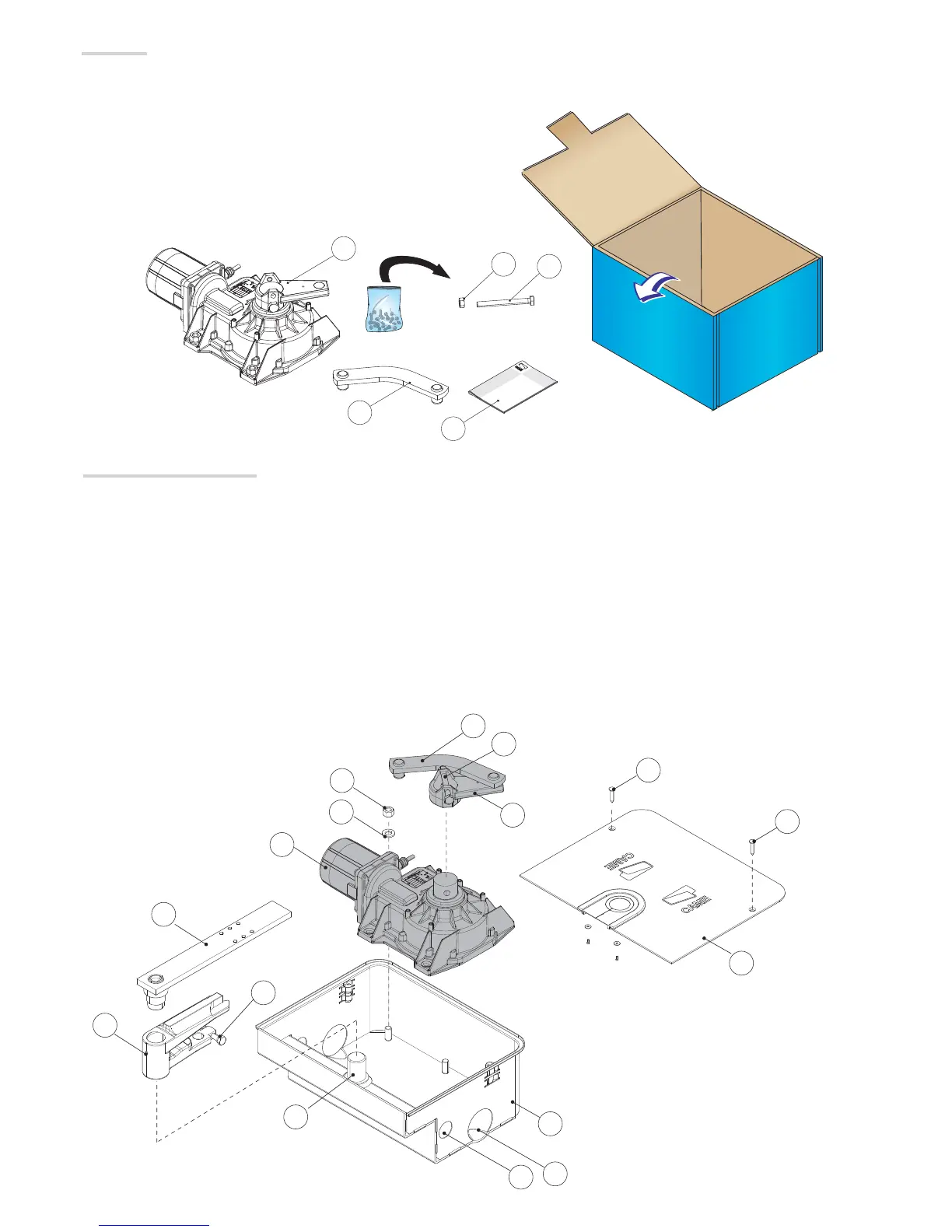
Description of the components
1. Gearmotor
2. Transmission lever
3. Gearmotor arm
4. Limit switch adjusting screw when closing
5. Couple release lever
6. Mounting bracket to gate
7. Limit switch adjusting screw when closing
8. Foundation box
9. Casing hole
10. Cover fixing screw
11. UNI 5588 M12 nut
12. UNI 6592 12 washer
13. Drainage hole
14. Cable routing hole
15. Pin
Packing list
1. 1 x Gearmotor
2. 1 x UNI 5588 M8 nut
3. 1 x UNI 5739 M4 x 100 screw
4. 1 x Transmission lever
5. 1 x installation manual

Questions and Answers:

Question and Answer IconNeed help?

Do you have a question about the CAME FROG-A and is the answer not in the manual?

CAME FROG-A Specifications

General IconGeneral
Max Gate Weight800 kg
Max Gate Length3.5 m
Power Supply230 V AC
Motor Voltage230 V AC
Duty Cycle30%
Operating Temperature-20°C to +55°C
Protection RatingIP67
Control TypeRemote Control

Related product manuals