7 02/2016
© CAME S.p.A. - The data and information provided in this manual are subject to change at any time without prior notice by CAME S.p.A.
INSTALLATION
⚠
The following illustrations are only examples, given that the space for securing the operator and accessories varies depending on the overall dimensions.
The installation technician is responsible for choosing the most suitable solution.
The following drawings refer to a standard installation of an inward opening gate.
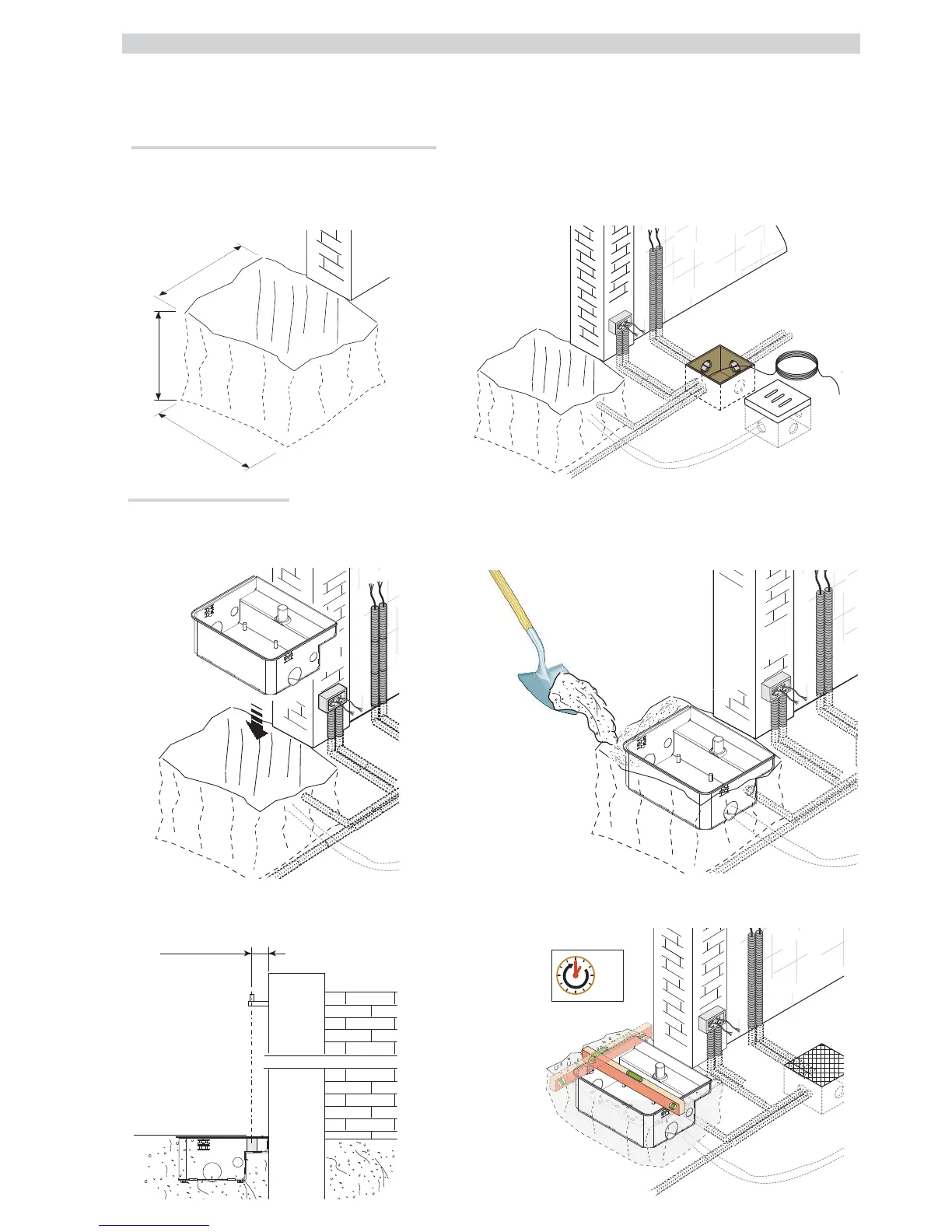
Laying the corrugated pipes and inspection chambers
Make the hole for the box.
Prepare the junction boxes and corrugated pipes necessary for connection to the inspection chamber and the drain pipe.
The number of tubes depends on the type of system installed and any accessories.
Installing the foundation box
Lean the box against the pillar making sure that the corrugated pipes and the drain pipe pass through the designated holes.
Fill the hole with concrete.
Position the box level with the ground and place the pin in line with the upper gate hinge. Wait at least 24h to cure.
Clean any remaining concrete from inside the box.