7 02/2016 © CAME S.p.A. - The data and information provided in this manual are subject to change at any time without prior notice by CAME S.p.A.
GENERAL INSTALLATION INSTRUCTIONS
⚠
Installation must be carried out by qualified and experienced personnel in compliance with applicable regulations.
Preliminary checks
⚠
Before installing the operator:
• Provide a suitable single-pole disconnection device, with a maximum of 3 mm between the contacts, to disconnect the power supply;
• Prepare suitable piping and ducts for routing the electrical cables, ensuring protection against mechanical damage;
• Prepare a drain pipe to prevent stagnation that may cause oxidation;
•
Make sure that any connections within the container (made to ensure the continuity of the protection circuit) are fitted with additional insulation
compared to the other internal conductor parts;
• Make sure the gate structure is sturdy enough, that the hinges are in proper working order and that there is no friction between the moving and fixed parts;
• Make sure there are opening and closing mechanical stops.
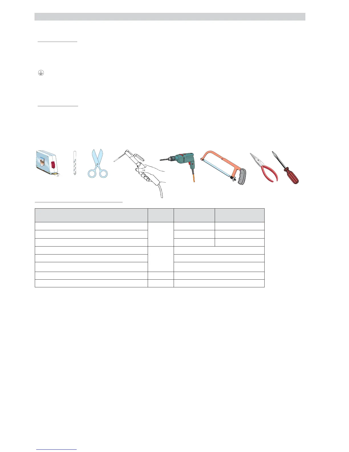
Tools and materials
Make sure you have all the tools and materials you will need for the installation at hand to work in total safety and compliance with current standards and
regulations. The figure shows some examples of installer’s tools.
Types of cables and minimum thicknesses
Connection Cable type
Cable length
1< 15 m
Cable length
15 < 30 m
Control panel power supply 230 V
H05RN-F
3G x 1,5 mm
2
3G x 2,5 mm
2
Motor power supply 230 V
4G x 1,5 mm
2
4G x 2,5 mm
2
Flashing light
2 x 0,5 mm
2
2 x 1,5 mm
2
Photocell transmitters FROR CEI
20-22
IEC EN
50267-2-1
2 x 0.5 mm
2
Photocell receivers 4 x 0.5 mm
2
Control and safety devices 2 x 0.5 mm
2
Encoder TWISTED max 30 m
Antenna RG58 max 10 m
N.B.: If the cables differ in length from what shown in the table, the cable cross-section is determined according to the actual current draw of the devices
connected and according to the provisions of the IEC EN 60204-1 standard.
For connections that require several, sequential loads, the sizes given on the table must be re-evaluated based on actual power draw and distances. When
connecting products that are not specified in this manual, please refer to the documentation provided with said products.