EasyManuals Logo

CAME FROG-A User Manual

CAME FROG-A
16 pages
To Next Page IconTo Next Page
To Previous Page IconTo Previous Page
Page #9 background imageLoading...
Page #9 background image
110° 110°110°
90°
90°
Ø 12
UNI 6592
Page
9
9 -
Manual code:
119AS45EN
119AS45 EN ver.
7
7 02/2016
© CAME S.p.A. - The data and information provided in this manual are subject to change at any time without prior notice by CAME S.p.A.
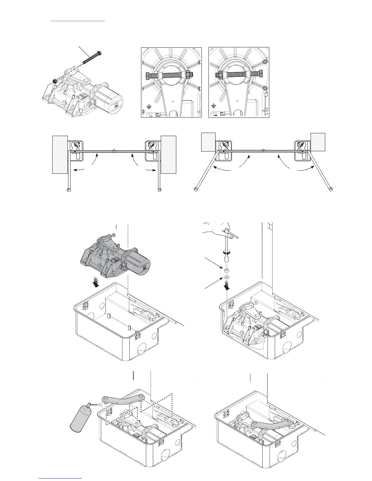
Open the leaf to simplify gearmotor installation and securing inside the foundation case.
Use studs and nuts (supplied).
Lubricate the transmission lever and push it into the holes of the gearmotor arm and case lever.
Fastening the gearmotor
Fit the adjusting bolt into the gearmotor. The direction in which to insert the bolt depends on the operator’s position.
LEFT SIDE RIGHT SIDE
LR
OUTER
entry
exit
INNER
R
OUTER
entry
exit
INNER
L

Questions and Answers:

Question and Answer IconNeed help?

Do you have a question about the CAME FROG-A and is the answer not in the manual?

CAME FROG-A Specifications

General IconGeneral
Max Gate Weight800 kg
Max Gate Length3.5 m
Power Supply230 V AC
Motor Voltage230 V AC
Duty Cycle30%
Operating Temperature-20°C to +55°C
Protection RatingIP67
Control TypeRemote Control

Related product manuals