Page 7 - Manual FA01569-EN - 04/2021 - © CAME S.p.A. - The contents of this manual may be changed at any time and without notice. - Translation of the original instructions
INSTALLATION
The following illustrations are examples only. The space available for fitting the operator and accessories varies depending on the area where it is
installed. It is up to the installer to find the most suitable solution.
The drawings refer to the right-side gearmotor.
Preliminary operations
The preliminary operations for installation concern the foundation box installation and the release devices fastening. Refer to the installation manuals for
these products.
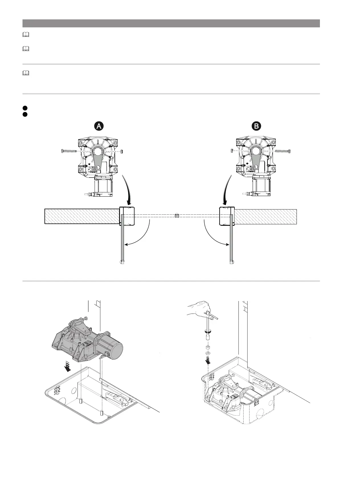
Setting up the gearmotor
Insert the closing limit-switch point adjustment screw into the gearmotor arm.
A
Gearmotor installed on the left
B
Gearmotor installed on the right
Fastening the gearmotor
Manually open the leaf.
Position the gearmotor over the threaded pins of the casing and fasten it.