17
19
18
4
5
14 13 9 7
16
2
10
11
12
6
21
3
8
22
3
26V
0V
230
0
20
1
15
p.
12 - Manual code:
FA01030-EN v.
1- 01/2018 - © Came S.p.A. - The manual's contents may be edited at any time without notice.
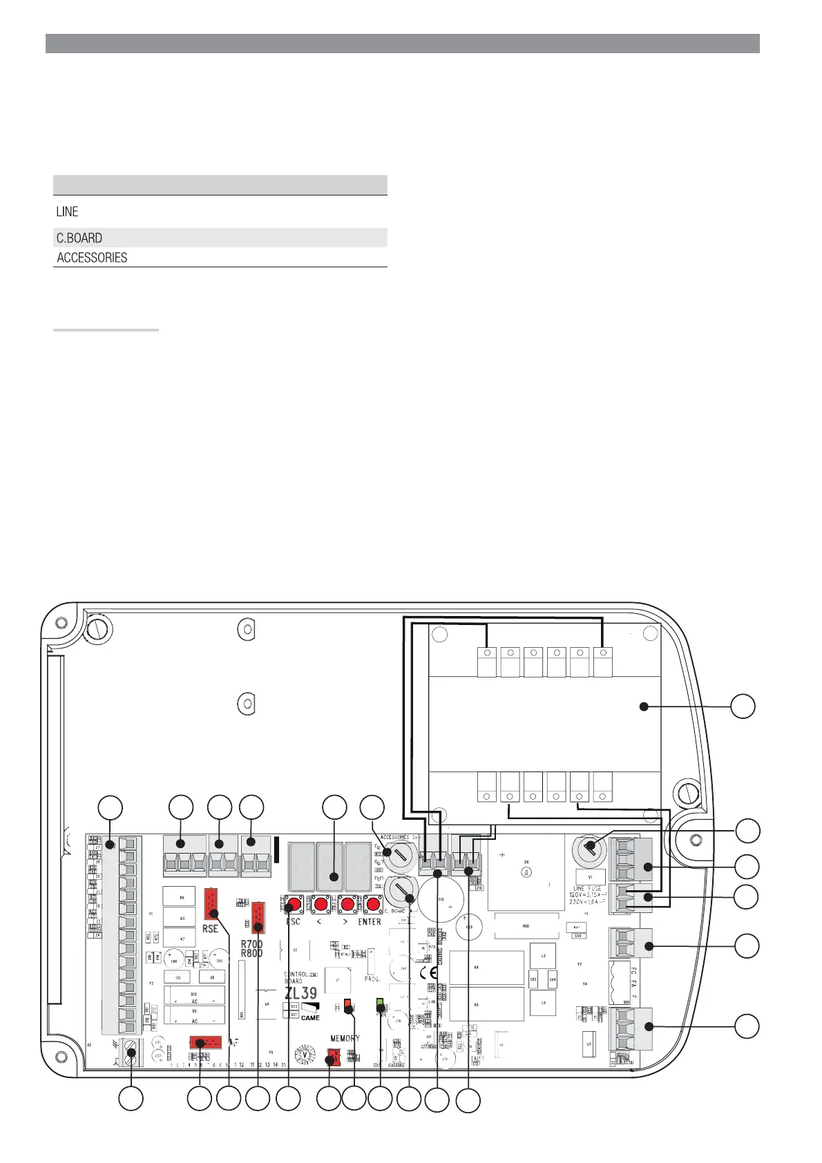
Description of parts
1. Transformer
2. Terminal board for power supply
3. Terminal board for transformer
4. Terminal board for gearmotor
5. Terminal board for encoder
6. Control-board fuse
7. Voltage signalling LED
8. Programming warning LED
9. Memory roll card connector
10. Programming buttons
11. R700 / R800 card connector
12. RSE card connector
13. AF card connector
14. Terminal board for antenna
15. Terminal board for control and safety devices
16. Terminal board for paired / alternate / CRP connection
17. Terminal board for keypad selector
18. Terminal board for transponder devices
19. Display
20. Accessories fuse
21. Line fuse
22. Terminal board for thermal cut-off switch
ELECTRICAL CONNECTIONS
⚠
Warning! Before working on the control panel, cut off the main current supply and remove any batteries.
Power supply to control panel and control devices: 24 V AC/DC.
The input and output contact functions, the timing settings and user management are set and shown on the display.All connections are quick-fuse
protected.
FUSE TABLE ZL39
- Line
3.15 A-F = 120 V
1.6 A-F = 230 V
- Control board
1 A-F
- Accessories
2 A-F
 Loading...


