4
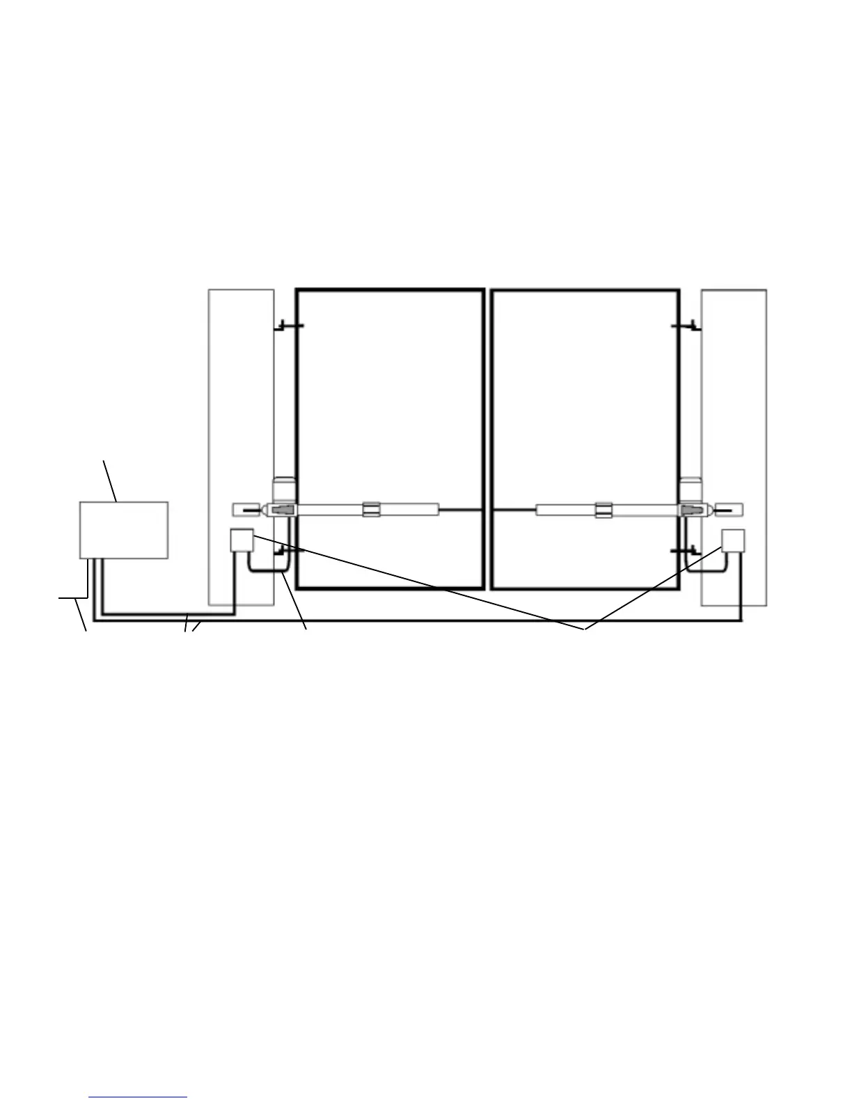
1.2 - Basic Cable Layout
This diagram details the basic cable layout for a pair of motors.
The power supply to the control panel should be live and protected in accordance with the 16th edition
electrical regulations. The supply should be rated at a minimum of 6 amps. When installing wires
outdoors the cable approach to all devices must be from below to create a ‘drip-loop’ and thereby
avoid unneccessary water ingress.
Fig 2
When installing low voltage cable around the gateway it is advised to put all low voltage cable in either
ducting ot alkathene piping. All cable jointing should be carried out above ground.
Control panel
housing
240V AC
4 core
1.5mm SWA
4 core
1.5mm flex
Joint box
 Loading...