STYLO-BD
➊
➋
➊
➋
56
80
12404012
4 x ø 8,5
108
640
24
3 x M9
50
50180 180180
18
➊
➋
➊
➌
Pag.
10 - Manual code:
119DV11 ver.
1.0 03/2010 © CAME cancelli automatici s.p.a. - The data and information reported in this installation manual are susceptible to change at any time and without obligation on CAME cancelli automatici s.p.a. to notify users.
ENGLISH
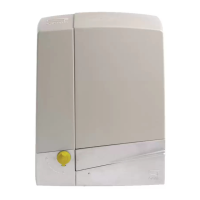
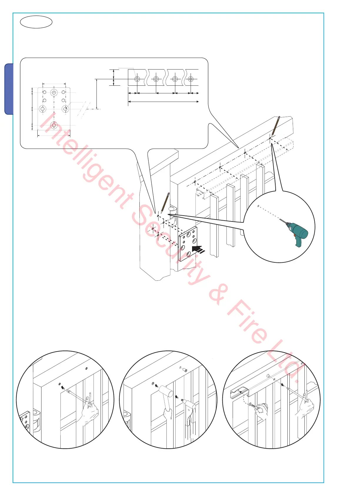
1b) position the gearmotor anchoring bracket and the slide rail following the measurements shown in the drawing.
Drill and thread the holes using an M8 male piece or use Ø 11 mm threaded inserts or any suitable materials for the rail to hold.
Note: the illustrations are mere examples, it is up to the installer to choose the most suitable solution depending on gate-leaf type
and thickness.
Position the slide rail in the holes and secure it using threaded cylinder head screws.
Intelligent Security & Fire Ltd.
 Loading...