STYLO-BS
56
80
12
404012
4 x ø 8,5
75
60
100
18
2 x ø 6,5
➊
➌
➊
➋
➌
Pag.
9 -
Manual code
:
119DV11 ver.
1.0 03/2010
© CAME cancelli automatici s.p.a. -
The data and information reported in this installation manual are susceptible to change at any time and without obligation on CAME cancelli automatici s.p.a. to notify users.
ENGLISH
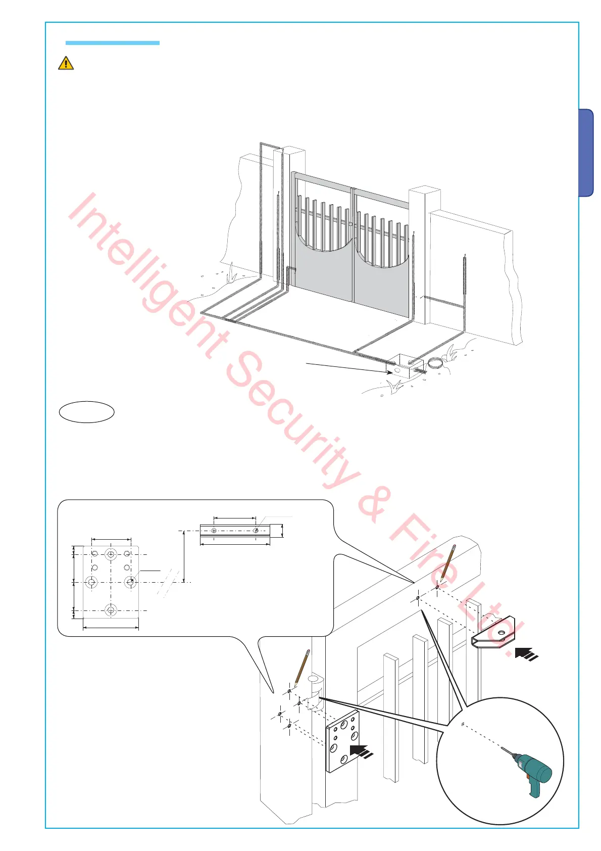
Set up corrugated tubes for the connections coming from the junction box.
N.B.: the number of tubes depends on the type of system installed and any accessories.
The following illustrations are only examples, given that the space for securing the automation and accessories varies depending
on the overall dimensions.
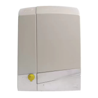
Installing the operator
Connection junction box.
1a) Trace all axis and dimensions, the secure the gearmotor anchoring bracket to the wall or post as well as the arm-to-gate anchoring bracket.
Note: the illustrations are mere examples, it is up to the installer to choose the most suitable solution depending on gate-leaf type and thickness.
Intelligent Security & Fire Ltd.
 Loading...