2
3
4
5
9
6
7
PROG
QUADRO COMANDO
ZR24
TCA TL
+-+-
UV WE1
10
11
12 7C1
E3
L1 L2
1
8
The data and information provided in this manual are subject to change at any time without prior notice.
Page
4 - Manual code:
319T07EN
ver.
3 05/2014 © CAME cancelli automatici S.p.A.
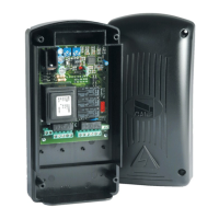
Description of the components
1. Connection terminal block
2. Line fuse
3. Devices and accessories fuse
4. Memorisation button
5. Operating time adjustment trimmer
6. ACT adjustment trimmer
7. DIP function selector
8. Connector for AF card
9. Indicator LED
⚠
Before intervening on the device, disconnect the line voltage.
 Loading...