2
3
4
5
9
6
7
PROG
QUADRO COMANDO
ZR24
TCA TL
+-+-
UV WE1
10
11
12 7C1
E3
L1 L2
1
8
I dati e le informazioni indicate in questo manuale sono da ritenersi suscettibili di modifica in qualsiasi momento e senza obbligo di preavviso.
Pag.
4 - Codice manuale:
319T07IT
ver.
3 05/2014 © CAME cancelli automatici s.p.a.
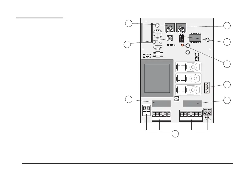
Descrizione delle parti
1. Morsettiere di collegamento
2. Fusibile di linea
3. Fusibile dispositivi e accessori
4. Pulsante memorizzazione
5. Trimmer di regolazione tempo lavoro
6. Trimmer di regolazione TCA
7. DIP per selezione funzioni
8. Connettore per scheda AF
9. LED di segnalazione
⚠
Prima di intervenire togliere la tensione.
 Loading...