17
Model 289A Differential Pressure Indicating Switch Section 3
2. Gently turn the knurled head of the screw clockwise, pushing the pin
against the movement shaft and lifting the pointer with the arms. Finger
pressure should be sufcient to pull the pointer free. If more pressure is
required, an Allen wrench (inserted into head of the screw) can be used.
However, care should be exercised to avoid breaking the pin.
HUB
MOVEMENT SHAFT
POINTER
HUB
Figure 3.3—Pointer puller (Part No. 9A-0163-0005B)
Indicator Calibration
A complete calibration of instrument is required whenever the DPU assembly
is replaced.
IMPORTANT: Review all procedures, WARNINGS/NOTICES in the Model 199 DPU
user manual (Appendix A) BEFORE performing this procedure.
1. Securely mount the instrument in an approximately level position and
connect the DPU (see the Model 199 DPU user manual in Appendix A).
2. Remove the bezel/lens assembly.
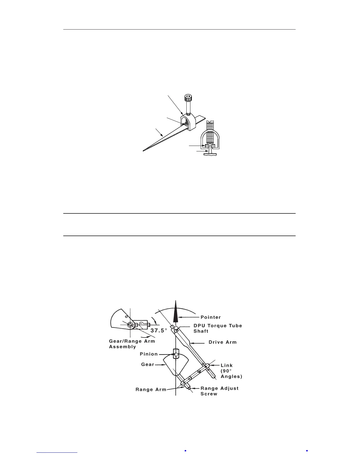
3. Align the linkage between the drive arm and the movement at 50% differ-
ential pressure (DP) as shown in Figure 3.4. Inspect parts for straightness
and pivot-t without binding.
Figure 3.4—Range/linearity adjustment (50% DP)