4
Section 1 Model 289A Differential Pressure Indicating Switch
Indicating Switch
(refer to Figure 1.2, Figures 2.1 to 2.6, and Table 2.1)
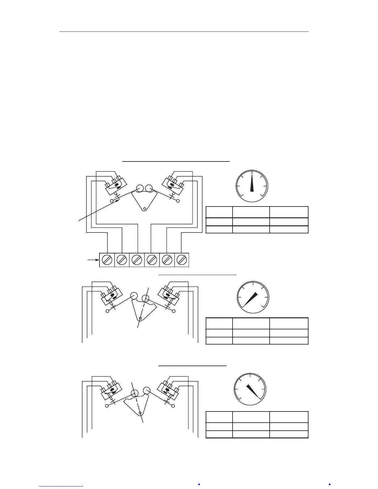
Rotation of the DPU torque tube shaft is coupled through connecting linkage
within the switch case to move the pointer across the scale plate. An actuat-
ing cam, directly connected to the torque tube shaft, rotates with the motion
of the shaft. Two cam follower roller/actuator arm assemblies, one for each
switch, respond to torque tube rotation by opening and closing the switches as
they ride on and off the cam. The levels of differential pressure at which the
switches actuate are adjustable with high and low alarm switch adjustments
on the scale plate.
RED
YELLOW
BLUE
BLACK
1000
50
ORANGE
VIOLET
SWITCH
CLOSED
CONTACTS
OPEN
CONTACTS
YELLOW & BLUE RED & YELLOW
VIOLET & ORANGE VIOLET & BLACK
A (LEFT)
B (RIGHT)
1000
50
Zero DP
SWITCH
CLOSED
CONTACTS
OPEN
CONTACTS
YELLOW & BLUERED & YELLOW
VIOLET & ORANGE VIOLET & BLACK
A (LEFT)
B (RIGHT)
1000
50
Maximum DP
SWITCH
CLOSED
CONTACTS
OPEN
CONTACTS
YELLOW & BLUE RED & YELLOW
VIOLET & ORANGEVIOLET & BLACK
A (LEFT)
B (RIGHT)
BOTH SWITCHES RELAXED
SWITCH “A” ACTUATED/SWITCH “B” RELAXED
SWITCH “A” RELAXED/SWITCH “B” ACTUATED
CAM
SWITCH