20
Section 3 Model 289A Differential Pressure Indicating Switch
Drive Arm Stop Adjustment
1. Apply sufcient pressure to the high-pressure housing to deect the
pointer against the full range stop snubber on the scale plate.
2. Slide the upper drive arm stop bracket against the drive arm and tighten
the drive arm stop bracket screw.
3. Apply sufcient pressure to the low pressure housing to deect the
pointer against the zero stop snubber on the scale plate.
4. Bend the zero drive arm stop against the drive arm.
5. Verify calibration as applicable.
SwitchCalibration
Before performing a complete calibration procedure, verify that the instru-
ment is out of calibration, by performing a calibration check procedure (page
15). If the instrument is out of calibration, before performing a complete
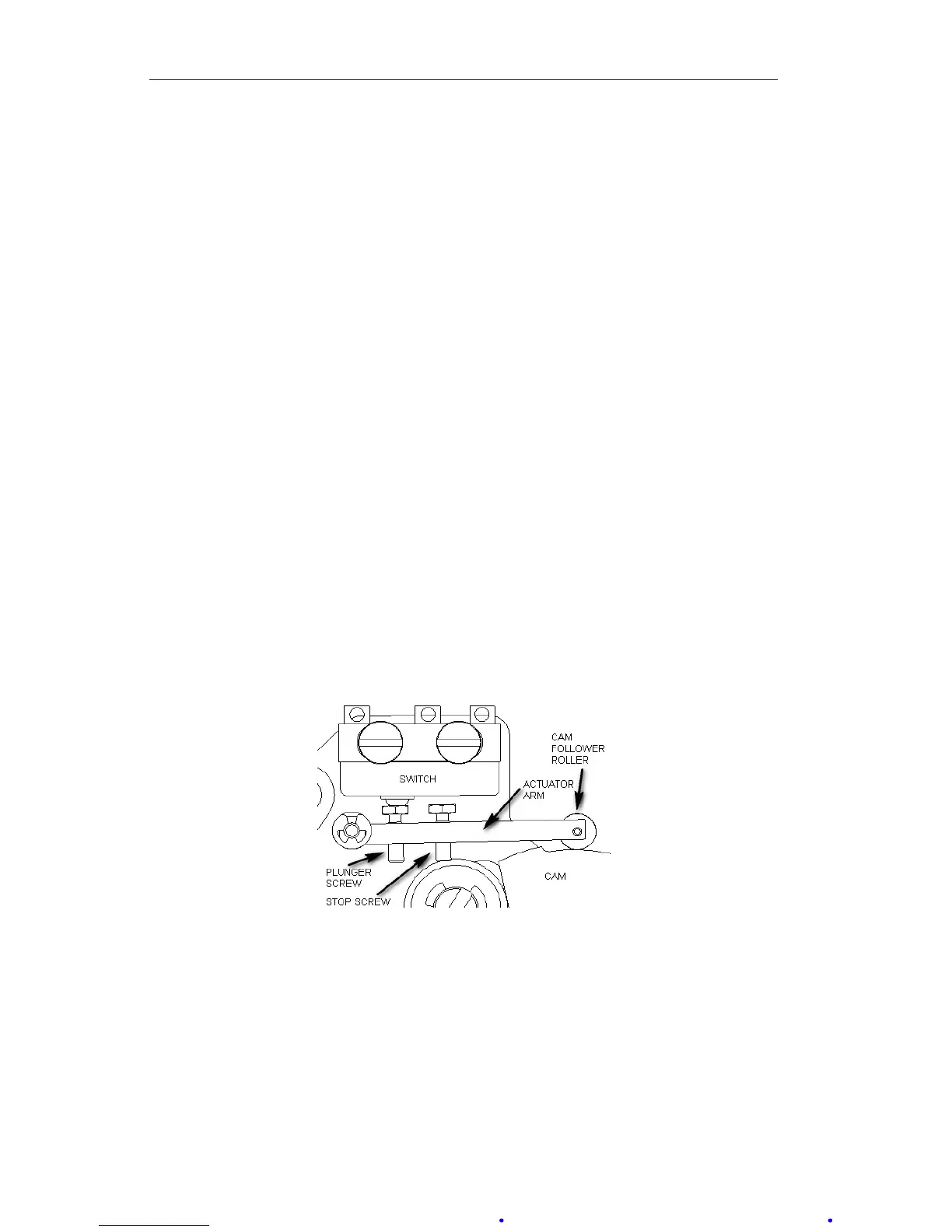
calibration procedure, remove the bezel/lens and scale plate and inspect the
switch mechanism (Figure 3.6) to verify the following:
• The roller rotates without wobble or binding.
• The cam is relatively centered under the roller.
• The actuator arm moves freely on its pivot.
• All switch mounting screws are tight.
• Linkages are straight and do not bind at the pivots.
Correct any problems that are observed.
Figure 3.6—Switch mechanism
Calibration Setup
1. Connect the lamp or buzzer to the switch output leads.
2. Connect a test voltage to the switch input terminals on the terminal strip.
(A low voltage is recommended for safety.) If a relay is installed in the
instrument, coil voltage must be applied to the switch.
3. Unlock the switch plate and move the plate until the roller is positioned
at the top of the cam.