Home
Cameron
Measuring Instruments
BARTON 289A
Page 72 (Section 6-Dimensional Drawings)
Cameron BARTON 289A - Section 6-Dimensional Drawings
75 pages
Manual
Save Page as PDF
To Next Page
To Next Page
To Previous Page
To Previous Page
Loading...
A-35
Model 199 Differential Pressure Unit (DPU)
Section 6
Section 6—Dimensional Drawings
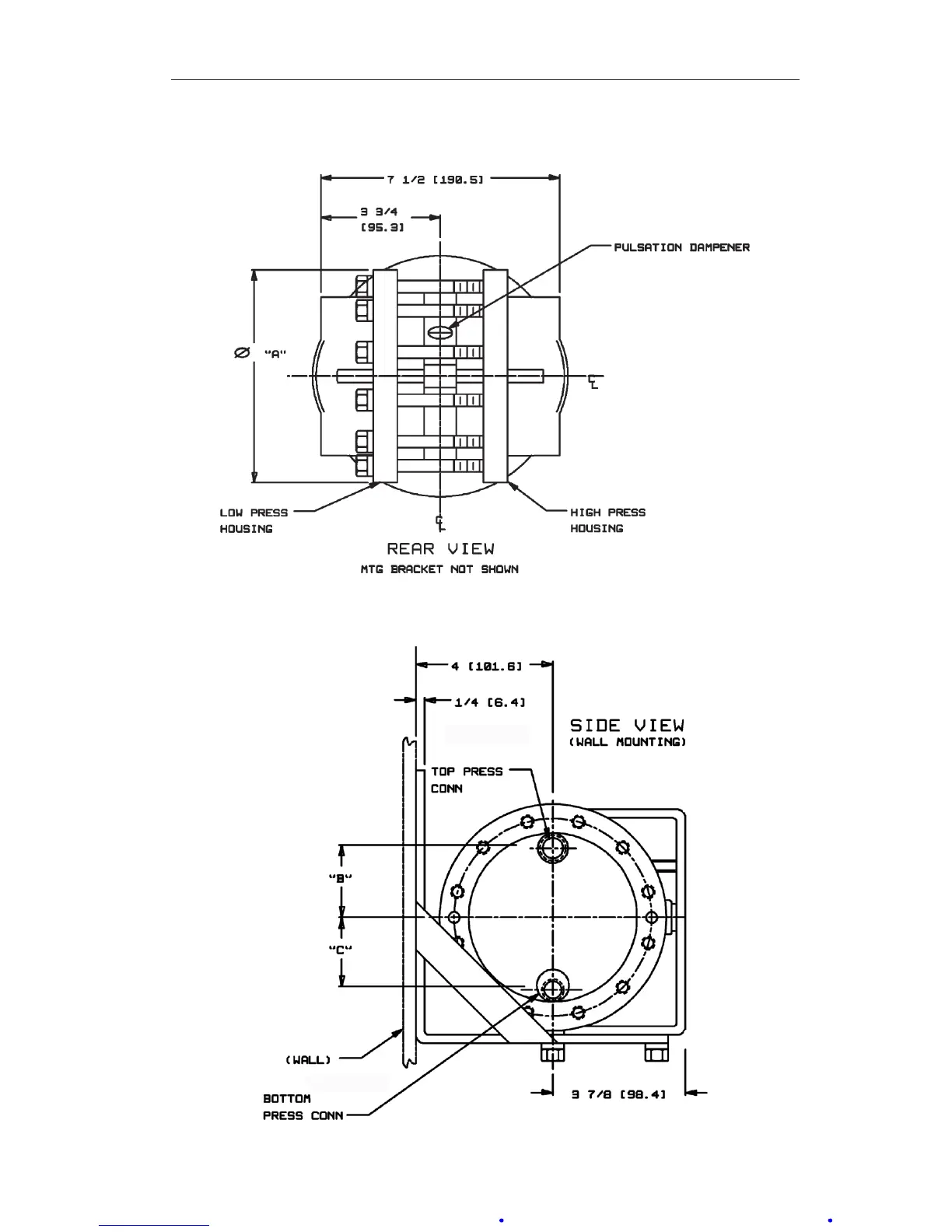
Figure 6.1—Dimensional drawing, Model 199 DPU, rear view
Figure 6.2—Dimensional drawing, Model 199 DPU, side view
71
73
Table of Contents
Main Page
Differential Pressure Indicating Switch User Manual
1
Default Chapter
1
Table of Contents
1
Safety
2
Section 1-Introduction
3
General
3
Main Components
3
Indicating Switch
4
Relays
5
Wiring
5
Differential Pressure Unit (DPU)
5
Specifications
5
Nuclear Qualifications
6
Section 2-Installation
7
General
7
Mounting/Piping/Dpu Installation
7
Electrical Connection (Switches/Relays)
7
Switch Use
7
Startup
8
Switch and Relay Wiring Diagrams
9
Section 3-Maintenance and Calibration
14
Tools
14
Bezel/Lens (or Cover) Installation and Removal
14
Calibration Check
15
Pointer Installation and Removal
16
Pointer Installation
16
Pointer Removal
16
Indicator Calibration
17
Drive Arm Tightness Test
19
Drive Arm Stop Adjustment
20
Switch Calibration
20
Calibration Setup
20
Calibration Procedure
21
Changing Switch Set Point
22
Definitions of Terms
22
Best Practices for Set Points
22
Changing Set Point of an In-Service Instrument (Not Recommended for Nuclear Qualified Units)
23
Changing Set Point of an Out-Of-Service Instrument
24
Range Changes
24
Parts Repalcement
25
Troubleshooting
26
Section 4-Assembly Drawing And Parts Lists
29
Section 5-Installation/Dimensional Drawings
35
Differential Pressure Unit (Dpu) User Manual
38
Default Chapter
39
Technical Support
39
Section 1-Introduction
40
General
40
Product Description
40
Specifications
41
Section 2-Theory of Operation
42
Basic Components
42
Pressure Housings
42
Bellows
42
Range Springs
44
Torque Tube Assembly
44
Pulsation Dampener
45
Section 3-Installation/Operation
46
Unpacking
46
Mounting
46
Flush or Panel Mounting
46
Piping-Standard Practices
46
All Applications (Flow and Liquid Level
46
Flow Applications
47
Liquid Level Applications
47
Piping Diagrams
48
General Startup Practice Considerations
54
Section 4-Maintenance, Adjustment, & Calibration
55
Tools Required for Maintenance and Calibration
55
DPU Inspection and Cleaning
55
Pressure Check Procedure
55
Inspection and Cleaning Procedure
56
Calibration Setup
57
Torque Tube Rotation Check (Replacement Units
58
Range Change
58
2-1/8-Inch Diameter Bellows
58
3-3/4-Inch Diameter Bellows Without Kickoff Spring (>47" W.C
59
3-3/4-Inch Diameter Bellows with Kickoff Spring
60
Setting Bellows Travel
62
Bellows Unit Assembly (BUA) Replacement
62
Attaching Drive Arm to Torque Tube
63
Drive Arm Tightness Test
64
Adjusting Pulsation Dampener
64
Troubleshooting
64
Section 5-Parts Drawing/List
67
Section 6-Dimensional Drawings
72
Other manuals for Cameron BARTON 289A
Installation Manual
32 pages
Related product manuals
Cameron Barton 199
32 pages
Cameron Scanner 2000 microEFM
190 pages
Cameron Scanner 3100 EFM
100 pages
Cameron NUFLO MC-III
120 pages
Cameron NUFLO MC-III EXP
143 pages
Cameron NuFlo MC-II
47 pages
Cameron NUFLO EZ-IN Series
32 pages