9
Model 289A Differential Pressure Indicating Switch Section 2
SwitchandRelayWiringDiagrams
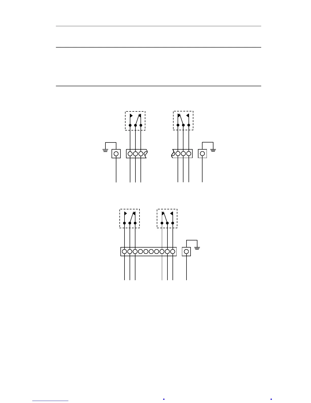
IMPORTANT: Figures 2.1 through 2.6 show: switch & relay contacts in the relaxed
(shelf) condition, the low switch set to trip at a position below the pointer
scale position, and the high switch set to trip at a position above the
pointer scale position. NO = Normally Open in (shelf) condition. NC =
Normally Closed in (shelf) condition. C= Common.
HIGH SPDT SWITCH
NOCNC
CASE GROUND
GREEN
ORANGE
VIOLET
BLACK
ORANGE
VIOLET
BLACK
8 9 10
LOW SPDT SWITCH
NO
1
2 3
C NC
RED
YELLOW
BLUE
RED
CASE GROUND
GREEN
YELLOW
BLUE
LOW & HIGH SPDT SWITCHES
NO NOC CNC NC
RED
YELLOW
BLUE
RED
CASE GROUND
GREEN
YELLOW
BLUE
ORANGE
VIOLET
BLACK
ORANGE
VIOLET
BLACK
1 2 3 4 5 6 7 8 9 10
Figure 2.1—Low/high SPDT switch diagrams
(current conguration color codes - see Table 2.1, page 8)