FINAL INSPECTION
vmr2006-012-100_ben
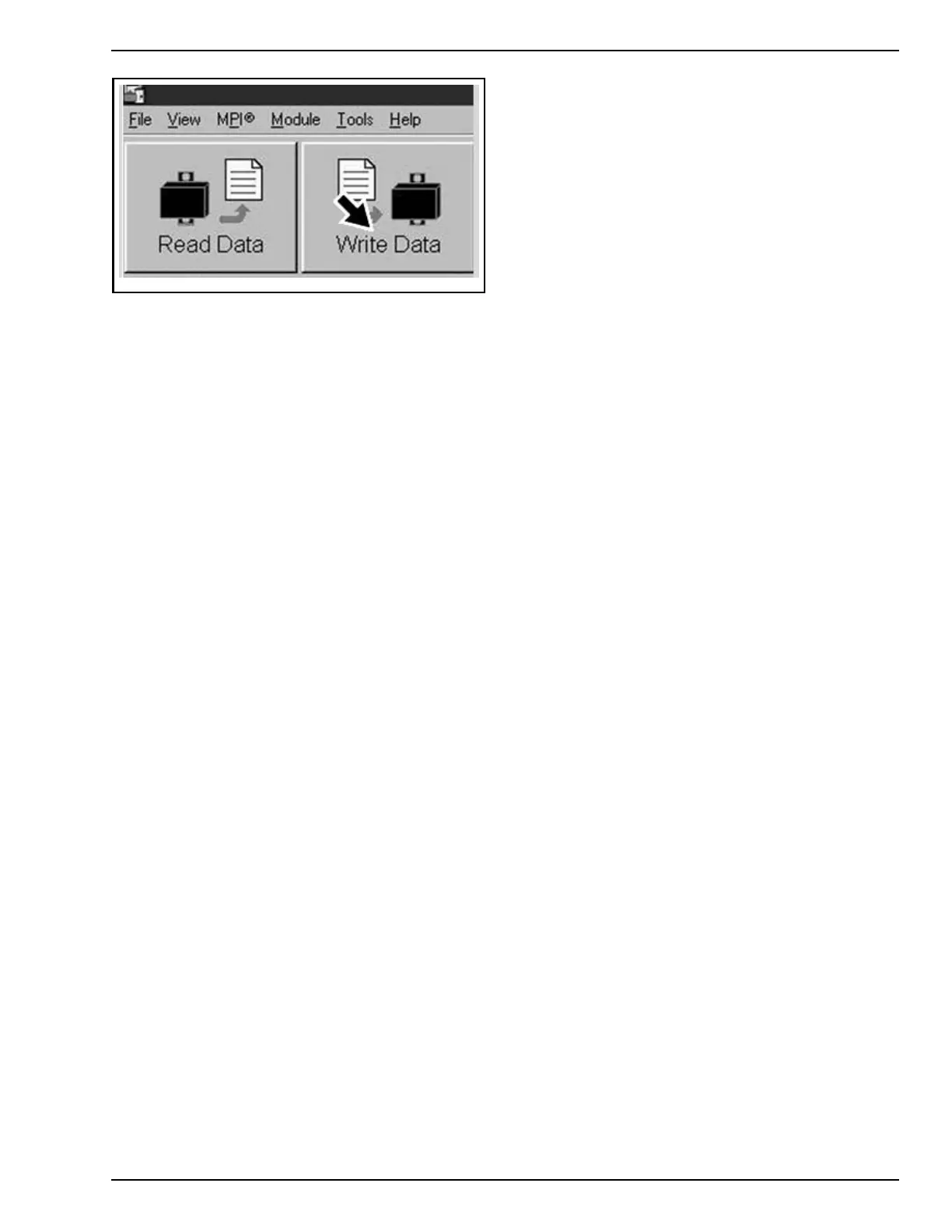
WRITE DATA BUTTON
3. Click on EXIT button (right most) to end session.
4. Reinstall DCL connector into its housing.
5. Reinstall service cover on vehicle.
Cluster Units and Clock Units
Setting
NOTE: Speed can be displayed in kilometers
(Km/h) or miles (MPH) per hour.
1. Turn ignition switch to ON.
2. Press the M button to stop the initial scrolling
message.
3. Press and hold the S button for three s econds.
– A scrolling message appears on the main dig-
ital display:
4. PUSH _M_ TO SELECT KM, _S_ TO SELECT
MI.
5. Once you have selected one of the two options
displayed. .
– A second scrolling message appears:
6. PUSH _M_ TO SELECT C°, _S_ TO SELECT F°.
7. Using the M button, toggle the secondary dis-
play to the clock function.
8. Press and hold the M button for three seconds,
the clock will blink 12 and 24 alternately.
9. When your choice is displayed, press the M
button to set it, the clock w ill blink the hour in-
dication.
10. Press the S button repeatedly until the proper
hour is displayed.
11. Press the M button to toggle to the minutes.
12. Press the S button repeatedly until the proper
minutes are displayed.
13. Press the M button and the display will stop
flashing and return to normal mode.
ASSEMBLY INSPECTION
Inspect the following parts to make sure that the
vehicle is properly assembled.
NOTE: Ensure that all protective materials are re-
moved from vehicle.
1. Front compartment cover and seat locks
2. Passenger grab handles
3. Front wheel lug nut torque (must be 105 N•m
(77 lbf•ft))
4. Suspension arm ball joint cotter pins
5. Tie rod end nuts and cotter pins
6. Rear axle nut and cotter pin
7. Gearshift pedal operation
8. Parking brake pedal and cable operation
9. Brake lines
10. Foot pegs.
NOTE: Refer to the Predelivery Check List to con-
firm that all i tems are covered by your inspection.
FINAL INSPECTION
Vehicle Test Run
Ride the vehicle to ensure proper operation of all
systems and components.
NOTE: It is normal for the shock absorbers not to
provide their optimal performance during the first
test ride. They will be set after a few suspension
strokes.
1. Instrument cluster operation and indica-
tor-warning pilot lamps functioning on power
up.
2. Display of safety message in cluster.
3. Starter interlock mechanism operation.
3.1 Press start button to make sure engine can
not be started if M button i s not depressed
to acknowledge safety message.
4. Cluster mode button and set button operation.
5. Check for error messages in cluster and correct
if necessary.
6. Verify that both ignition keys allow the engine
to start.
7. Brake operation.
– The brake pedal is in front of the right foot-
peg.
PREDELIVERY 2012-1 27 / 37
 Loading...