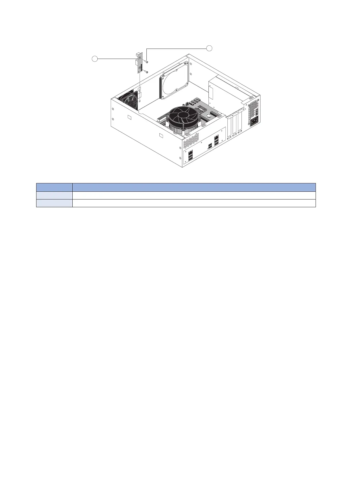
4. Remove the two screws that secure the service board to the chassis, and remove the board from the chassis (see
below figure).
Figure 21: Removing/replacing the service board
No. Name
1 Service board
2 Screw (1 of 2)
● To replace the service board
1. If you are replacing the old service board with a new one, unpack the new board and cable.
2. Position the new service board inside the chassis, fitting the LED display and service switches through the cutouts
in the chassis.
3. Secure the service board to the chassis using the two screws that you removed earlier (see above figure).
4. Connect the service board cable to the connector on the service board. The cable is keyed to fit in the connector
only one way.
5. Connect the free end of the service board cable to connector Port 80 Header (EFI GPIO Header, J4) on the
motherboard.
The cable is keyed to fit in the connector only one way.
6. Make sure that the service switches are set to the OFF position (both switches are away from ON). See “imagePRESS
Server connector panel and LED diagnostic codest” on page 17.
7. Reassemble the imagePRESS Server and verify its functionality (see “To reinstall and verify the imagePRESS Server”
on page 43).
■ Chassis fan
One chassis fan is installed in the imagePRESS Server, near the service board. Use the following procedures to remove or
replace the fan.
● To remove the chassis fan
1. Access and open the imagePRESS Server, as described on “Accessing the imagePRESS Server” on page 18.
2. Disconnect the 4-pin fan cable connector from the motherboard.
3. REPLACING PARTS
36