9
AC Output Relay Board(s)
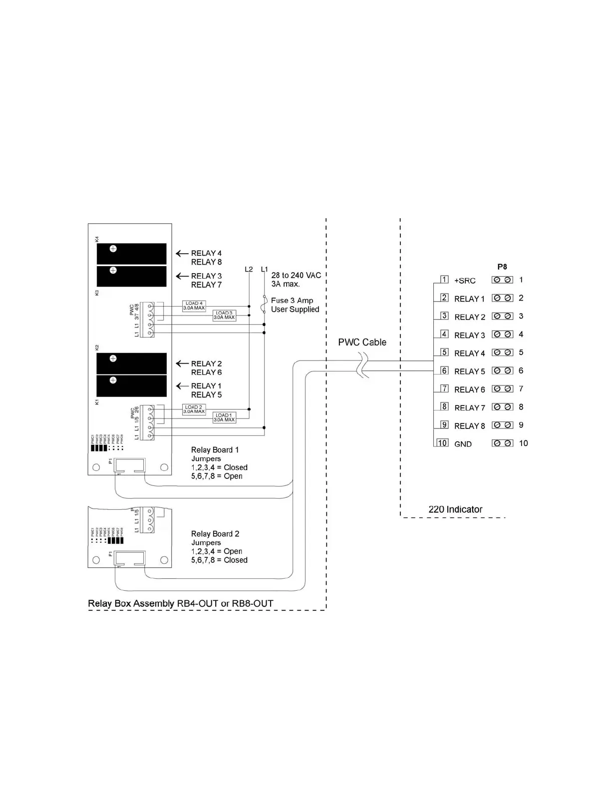
The AC Output Relay Board(s) are mounted in an external junction box for use with the 220
Indicator. The RB4-OUT contains one board and supports 4 outputs (jumper selectable). The
RB8-OUT contains two boards and supports 8 outputs. The relay board used in both is (Cardinal
p/n 8539-C062-0A). Connect the devices to be controlled as shown in Figure No. 6.
The individual relays can be configured to be on (closed) or off (open) at weights under the preset
weight then switch at the preset weight from on-to-off or off-to-on by setting the under weight
condition to on or off during setup and calibration or setup review.
• OUTPUT (closed) ........ 28-240VAC @ 3A maximum for each plug-in relay.
•
CONTROL INPUT ....... 5VDC @ 12mA from the 220 main pc board assembly P8.
• CONNECTION ............ Removable plug-in screw terminals for up to 14 AWG wire.
NOTE!
All relays are the normally-open type that will open when power to indicator is lost.
Re-Installing The Rear Panel
After all terminations have been made, remove the excess cable from the instrument enclosure
and securely tighten each of the cable gland connectors. Do not over-tighten these connectors but
make certain they are snug.
DO NOT USE TOOLS!
Finger tighten only! Ensure any unused
gland connectors are plugged. Replace the rear panel and secure with the 14 acorn nuts removed
earlier.
NOTE!
Follow a diagonal pattern when tightening the acorn nuts.
Figure No. 6