6
4. Connect each of the wires to terminal block
P6 referring to the table on the circuit board
for terminal connections. Refer to Figure
No. 7 for terminal block location.
5. To terminate a wire, first press down on the
release bar for the terminal, insert the wire
into the terminal opening then allow the
release bar to return to its original position,
locking the wire in place.
6. Repeat the procedure until all of the wires
are in place.
7. Route the load cell cable through the two Figure No. 3
cable clips provided on the upper and left
sides of the enclosure interior.
LOAD CELL CONNECTOR P7
PIN NO. Function PIN NO. Function
1 + EXCITATION 5 - SIGNAL
2 + SENSE 6 - SENSE
3 + SIGNAL 7 - EXCITATION
4 SHIELD
Load Cell Connections With Over 30 Feet Of Cable
For installations with over 30 feet of cable between the indicator and the load cells, sense wires
should be used. The sense wires must be connected between the +SENS, -SENS terminals on the
indicator and the +EXCITATION, -EXCITATION wires of the load cells or the +SENS, -SENS
terminals of the load cell trim board or the section seal trim board. For the indicator to use the
sense wires, the +SENS jumper J12 and the -SENS jumper J13 must be open (see Figure No. 7).
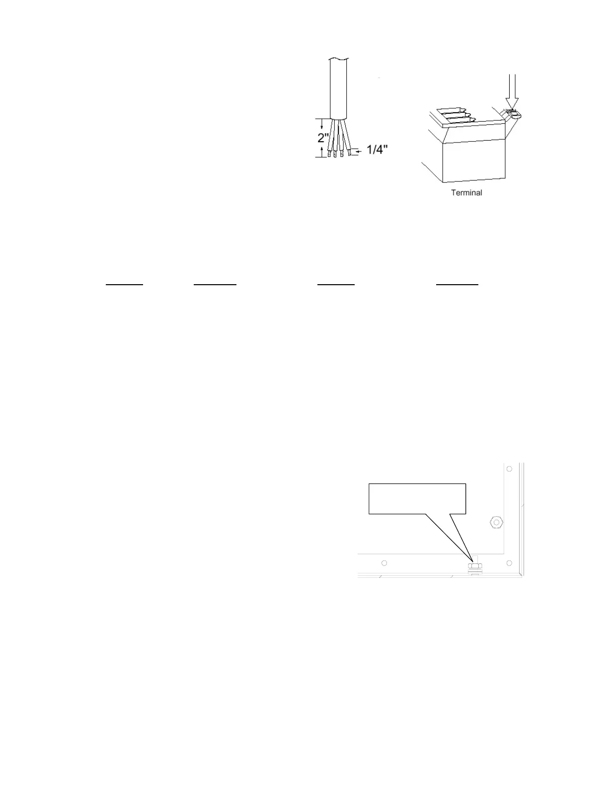
Load Cell Cable Shield Wire Connection
The load cell cable shield wire should be connected to the
threaded stud inside the indicator. This stud is located on
the bottom inside of the indicator near the load cell
connector P7. See Figure No.4.
The shield wire should be wrapped around the stud
between the 2 flat washers and secured using the hex nut.
Figure No. 4
Serial I/O Cable Installation
The 220 may be connected to a printer to record weight and associated data or it may be
connected to a remote display or even to a computer for transmission of weight data. The
weight data may be transmitted on demand (pressing the PRINT key or on receipt of a
command from the computer). For complete details on the 220 Serial I/O, refer to the
Setup, SIO Serial I/O section of the 220 Weight Indicating Instrument Technical and
Operation Manual, 8200-M502-O1.
1. Loosen the cable gland connector(s) for the serial cable. The gland connector(s) for the
serial data are located on the rear panel of the enclosure. Refer to Figure No. 2 for an
illustration of the gland connector layout.
2. Slip the serial cable through the gland connector and into the enclosure.
Threaded Stud for
Shield Wire