EasyManuals Logo

Carel pCO Series Application Program

Carel pCO Series
36 pages
To Next Page IconTo Next Page
To Previous Page IconTo Previous Page
Page #34 background imageLoading...
Page #34 background image
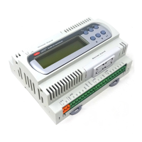
Carel srl: pCO Stage Controller
page 33
Refrigerator unit consisting of:
3 compressors
2 pressure probes
fans inverter
ID11R ID11 ID12R ID12
J21
GG0
J17
VG0 VG1 Y1 Y0
J20
NO12 C12 NO5 C5
J6
NO4 C4 NO3 C3 NO2 C2 NO1 C1
J5
ID1 ID2 ID3 ID4
J4
ID5 IDCM1
B1 AVSS B2 B3
J2
AVSS B4 B5 AVSS B6
J1
+24V
BCP1
24V~
BCP2 BCP3
BFINV
220V~
LP
HP
24V~
CMP3 CMP2 CMP1
F
N
K K K
FINV
PP1 PP2
POWER SUPPLY
ANALOG INPUTS
DIGITAL OUTPUTS
DIGITAL INPUTS
NO11 C11 NO10 C10
J22
NO9 C9
AL
F
N
AND
ANALOG OUTPUS
INPUTS OUTPUTS
BCP compressor lock device AL general alarm
BFINV fans inverter lock device CMP compressor
HP general high pressure switch FINV fans inverter (output 0¸10 volts) or RGF C.AR.EL.
LP general low pressure switch
PP pressure probe
F phase N neuter
Other manuals for Carel pCO Series

Questions and Answers:

Question and Answer IconNeed help?

Do you have a question about the Carel pCO Series and is the answer not in the manual?

Carel pCO Series Specifications

General IconGeneral
ConnectivityRS-485, Ethernet
DisplayLCD
Input/OutputConfigurable
Power Supply24 VAC/DC
TypeProgrammable Controller
Analog OutputsUp to 4
Serial CommunicationRS-485
ProtocolsModbus
Input Voltage24 VAC/DC
Protection RatingIP20
CommunicationRS-485, Ethernet
Relay OutputsUp to 8

Related product manuals