Carel srl: pCO Stage Controller
page 34
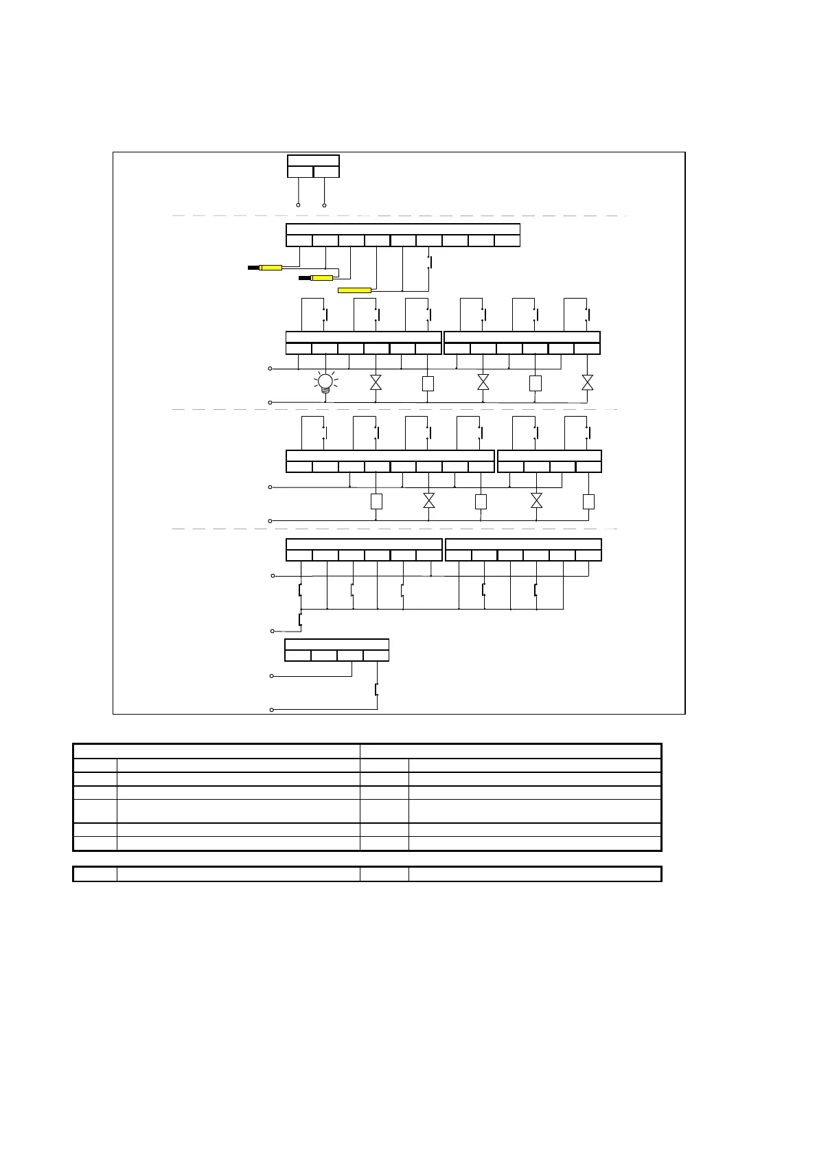
Chiller unit consisting of:
•
5 Compressors
•
2 NTC temperature probes
•
1 Stage of voltage control for comp.
•
1 External air temperature probe
•
remote On/Off from analog input
(compensation)
ID11R ID11 ID12R ID12
J21
GG0
J17
NO11 C11 NO10 C10
J22
NO9 C9
NO12 C12 NO5 C5
J6
NO4 C4 NO3 C3 NO2 C2 NO1 C1
J5
ID1 ID2 ID3 ID4
J4
ID5 IDCM1
B1 AVSS B2 B3
J2
AVSS B4 B5 AVSS B6
BCP1
24V~
BCP2
220V~
FLX
AF
24V~
CMP2 CMP1
AL
F
N
F
N
K K
P1C2 P1C1
ON/OFF
TAPTPP2TPP1
POWER SUPPLY
ANALOG INPUTS
DIGITAL OUTPUTS
DIGITAL INPUTS
CMP3
K
P1C3
NO8 C8 NC7 C7
J24
NO6 C6
CMP4
K
P1C4
CMP5
K
P1C5
ID6 ID7 ID8 ID9
J3
ID10 IDCM2
BCP3
BCP4
BCP5
INPUTS OUTPUTS
AF antifreeze lock AL general alarm
BCP compressor lock device CINV compressor 1/valve inverter
FLX flow switch CMP compressor
ON/OF
F
On/Off remote input P1C first stage of voltage control
TAP ambient air temperature probe
TPP temperature passive probe (IN/OUT)
F phase N neuter
Note:
Fans must be electromechanically controlled by means of a contact of the contactor of its compressor, or they
must be controlled through an external pressure switch (e.g. RFG or another pressure switch).

 Loading...


