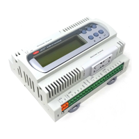
Carel srl: pCO Stage Controller
page 7
C12
range-end hour with secondary set (only if P41=1) 24 0÷24 h
C13 Sunday with secondary set (only if P41=1) 0
0
→
no; 1
→
yes
C14 Monday with secondary set (only if P41=1) 0
0
→
no; 1
→
yes
C15 Tuesday with secondary set (only if P41=1) 0
0
→
no; 1
→
yes
C16 Wednesday with secondary set (only if P41=1) 0
0
→
no; 1
→
yes
C17 Thursday with secondary set (only if P41=1) 0
0
→
no; 1
→
yes
C18 Friday with secondary set (only if P41=1) 0
0
→
no; 1
→
yes
C19 Saturday with secondary set (only if P41=1) 0
0
→
no; 1
→
yes
C20
half an hour exclusion (only if P41=1) 0 0÷7
C21
exclusion beginning (only if P41=1) 0 C11÷C12 h
C22
exclusion end (only if P41=1) 0 C21÷C12 h
Setpoint button
Code Description Def
ault
Rating Unit of
measure
Sd1 display of the probe 1 actual setpoint (enabled code in case of
setpoint control through analog input or if a secondary setpoint
is present or, finally, when the compensation is active)
St3÷St4 °C/°F/bar
St1 selection of probe 1 setpoint (only if P1>0 and P4>0) 2.5 St3÷St4 °C/°F/bar
St2 selection of probe 2 setpoint (only if P24>0 and P27>0)
16.0
St5÷St6 °C/°F/bar
Si1 setpoint selection of the probe 1/valve inverter (only if P20=1
and P14=1)
2.5 St3÷St4 °C/°F/bar
Si2 selection of fan inverter setpoint (only if P35=1)
16.0
St5÷St6 °C/°F/bar
PSS
password that allows access to the subsequent parameters 0 0÷999
St3
selection of the probe 1 minimum setpoint (only if P1>0) 0 -99÷99.9 °C/°F/bar
St4
selection of probe 1 maximum setpoint (only if P1>0) 5.0 -99÷99.9 °C/°F/bar
St5
selection of probe 2 minimum setpoint (only if P24>0)
10.0
-99÷99.9 °C/°F/bar
St6
selection of probe 2 maximum setpoint (only if P24>0)
24.0
-99÷99.9 °C/°F/bar
St7
secondary setpoint selection (only if at least a device of the
circuit 1 is present)
3.0 -99÷99.9 °C/°F/bar
d1
probe 1 differential selection (only if P1>0) 0.5 0÷20.0 °C/°F/bar
d2
probe 2 differential selection (only if P24>0) 2.0 0÷20.0 °C/°F/bar
d3
device 1/valve inverter differential (only if P1>0 and P14=1) 1.0 0÷20.0 °C/°F/bar
d4
selection of the fan inverter differential (only if P35=1) 2.0 0÷20.0 °C/°F/bar
Sr1
step of the device 1 inverter (only if P20=1 and P14=0) 0.2 0÷10.0 Volt
Sr2
selec. of the probe 1 inverter deviation (only if P20=1 and
P14=0)
0 0÷20.0 °C/°F/bar
Sr3
minimum aperture of the device 1 inverter (only if P20=1) 0 0÷10.0 Volt
Sr4
minim. aperture of the device 1 inverter always applied (only if
P20=1)
0
0→disable
1→enable
SH1
threshold of high for the probe 1 (only if P1>0) 5.0 -99÷99.9 °C/°F/bar
SL1
threshold of low for the probe 1 (only if P1>0) 1.0 -99÷99.9 °C/°F/bar
SH2
threshold of high for the probe 2 (only if P24>0)
20.0
-99÷99.9 °C/°F/bar
SL2
threshold of high for the probe 2 (only if P24>0) 0 -99÷99.9 °C/°F/bar
dH1 alarm delay of high for the probe 1 (only if P1>0) 0 0÷999 min
dL1 alarm delay of high for the probe 2 (only if P24>0) 0 0÷999 min
dH2 alarm delay of low for the probe 2 (only if P24>0) 0 0÷999 min
dL2 alarm delay of low for the probe 2 (only if P24>0) 0 0÷999 min
SC
compensation setpoint (only if P21=1)
25.0
-99÷99.9 °C/°F/bar
dC
compensation differential (only if P21=1) 5.0 -50.0÷50.0 °C/°F/bar
dt
delta of compensation (only if P21=1) 2.0 -99÷99.9 °C/°F/bar

 Loading...