Modular Standard HP Chiller for Carel driver
Carel code +030221236- Rel. 1.0 dated 7 July 2003
12
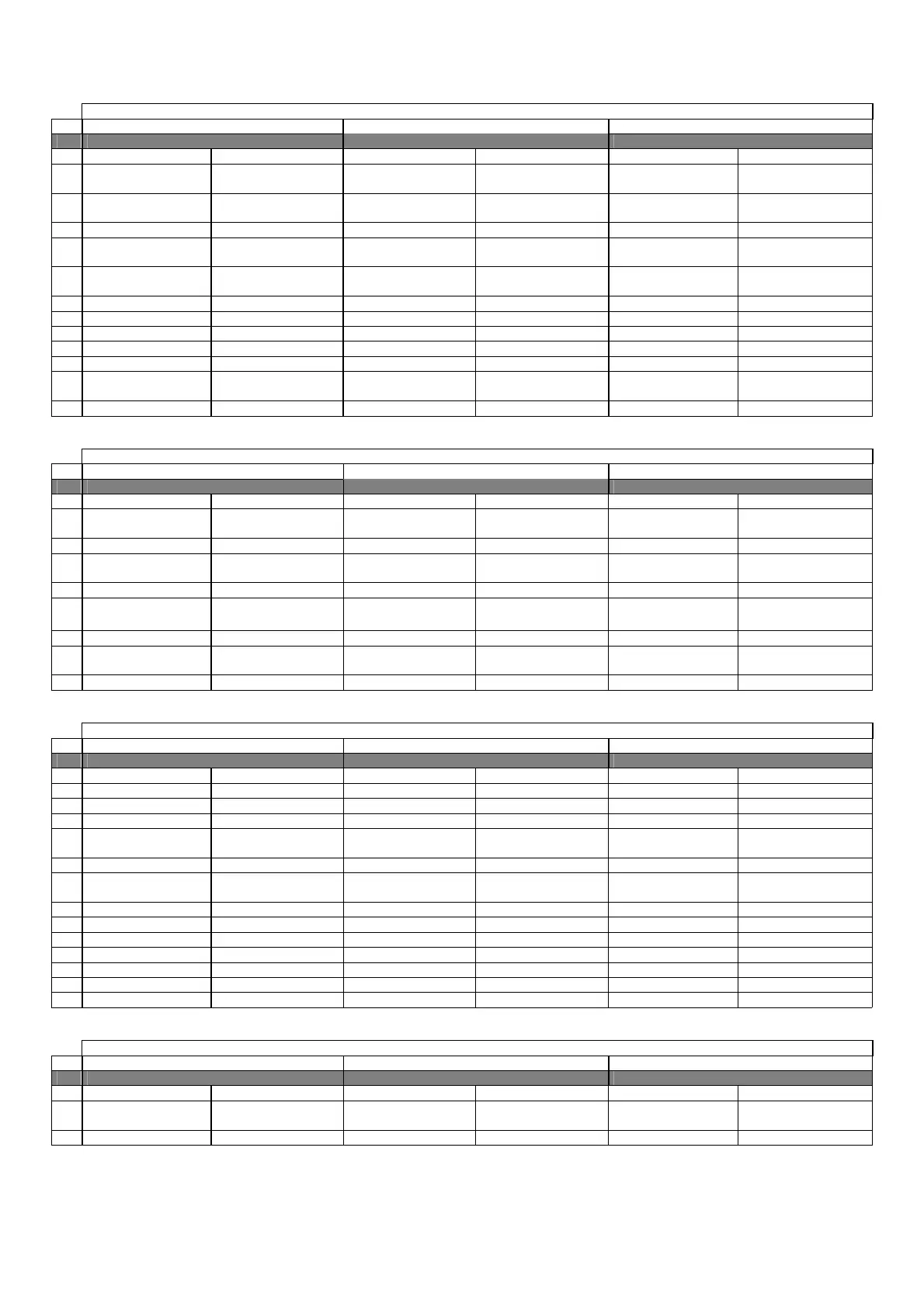
6.5 CHILLER UNIT WITH HEAT PUMP – MACHINE TYPE “4”
6.5.1 DIGITAL INPUTS
Chiller unit with heat pump MACHINE TYPE “4”
N. pCO2 MEDIUM pCO1 MEDIUM pCOC MEDIUM
Master Slave
Master Slave Master Slave
1
Serious alarm Serious alarm
(enablable)
Serious alarm Serious alarm
(enablable)
Serious alarm Serious alarm
(enablable)
2
Evaporator flow-switch Evaporator flow-switch
(enablable)
Evaporator flow-switch Evaporator flow-switch
(enablable)
Evaporator flow-switch Evaporator flow-switch
(enablable)
3
Remote On/Off Remote On/Off Remote On/Off
4
Cooling/heating
selector
Cooling/heating
selector
Cooling/heating
selector
5
Low pressure 1
pressure-switch
Low pressure 2
pressure-switch
Low pressure 1
pressure-switch
Low pressure 2
pressure-switch
Low pressure 1
pressure-switch
Low pressure 2
pressure-switch
6
Oil differential 1 Oil differential 2 Oil differential 1 Oil differential 2 Oil differential 1 Oil differential 2
7
Fan 1 thermal cutout Fan 1 thermal cutout Fan 1 thermal cutout Fan 1 thermal cutout Fan 1 thermal cutout Fan 1 thermal cutout
8
Fan 2 thermal cutout Fan 2 thermal cutout Fan 2 thermal cutout Fan 2 thermal cutout Fan 2 thermal cutout Fan 2 thermal cutout
9
Fan 3 thermal cutout Fan 3 thermal cutout Fan 3 thermal cutout Fan 3 thermal cutout Fan 3 thermal cutout Fan 3 thermal cutout
10
Pump thermal cutout Pump thermal cutout Pump thermal cutout
11
High pressure 1
pressure-switch
High pressure 2
pressure-switch
High pressure 1
pressure-switch
High pressure 2
pressure-switch
High pressure 1
pressure-switch
High pressure 2
pressure-switch
12
Comp. 1 thermal cutout Comp. 2 thermal cutout Comp. 1 thermal cutout Comp. 2 thermal cutout Comp. 1 thermal cutout Comp. 2 thermal cutout
6.5.2 ANALOGUE INPUTS
Chiller unit with heat pump MACHINE TYPE “4”
N. pCO2 MEDIUM pCO1 MEDIUM pCOC MEDIUM
Master Slave
Master Slave Master Slave
1
Circ. 1 condenser
temperature
Circ. 2 condenser
temperature
Outside set point Water inlet temperature
2
Water outlet temp.1 Water outlet temp.2
3
Circuit 1 high pressure
transducer
Circuit 2 high pressure
transducer
Circ. 1 condenser
temperature
Circ. 2 condenser
temperature
4
Water inlet temperature
5
Water outlet temp.1 Water outlet temp.2
Water inlet
temperature
Outside set-point
6
Outside set-point Water outlet temp.1 Water outlet temp.2
7
Circuit 1 high pressure
transducer
Circuit 2 high pressure
transducer
Circ. 1 condenser
temperature
Circ. 2 condenser
temperature
Circuit 1 high pressure
transducer
Circuit 2 high pressure
transducer
8
6.5.3 DIGITAL OUTPUTS
Chiller unit with heat pump MACHINE TYPE “4”
N. pCO2 MEDIUM pCO1 MEDIUM pCOC MEDIUM
Master Slave
Master Slave Master Slave
1
Circulation pump Circulation pump Circulation pump
2
Comp. 1 winding A Comp. 2 winding A Comp. 1 winding A Comp. 2 winding A Comp. 1 winding A Comp. 2 winding A
3
Comp. 1 winding B Comp. 2 winding B Comp. 1 winding B Comp. 2 winding B Comp. 1 winding B Comp. 2 winding B
4
Circuit 1 liquid
solenoid
Circuit 2 liquid solenoid Circuit 1 liquid solenoid Circuit 2 liquid solenoid Circuit 1 liquid
solenoid
Circuit 2 liquid solenoid
5
Circuit 1 4-way valve Circuit 2 4-way valve Circuit 1 4-way valve Circuit 2 4-way valve Circuit 1 4-way valve Circuit 2 4-way valve
6
Comp. 1 capacity stage
1
Comp. 2 capacity stage 1 Comp. 1 capacity stage
1
Comp. 2 capacity stage 1 Comp. 1 capacity stage
1
Comp. 2 capacity stage 1
7
Comp. 1 capacity stage 2 Comp. 2 capacity stage 2 Comp. 1 capacity stage 2 Comp. 2 capacity stage 2 Comp. 1 capacity stage 2 Comp. 2 capacity stage 2
8
Comp. 1 capacity stage 3 Comp. 2 capacity stage 3 Comp. 1 capacity stage 3 Comp. 2 capacity stage 3 Comp. 1 capacity stage 3 Comp. 2 capacity stage 3
9
Circuit 1 fan 2 Circuit 2 fan 2 Circuit 1 fan 2 Circuit 2 fan 2 Circuit 1 fan 2 Circuit 2 fan 2
10
Antifreeze heater Antifreeze heater Antifreeze heater Antifreeze heater Antifreeze heater Antifreeze heater
11
General alarm General alarm General alarm General alarm General alarm General alarm
12
Circuit 1 fan 1 Circuit 2 fan 1 Circuit 1 fan 1 Circuit 2 fan 1 Circuit 1 fan 1 Circuit 2 fan 1
13
Circuit 1 fan 3 Circuit 2 fan 3 Circuit 1 fan 3 Circuit 2 fan 3 Circuit 1 fan 3 Circuit 2 fan 3
6.5.4 ANALOGUE OUTPUTS
Chiller unit with heat pump MACHINE TYPE “4”
N. pCO2 MEDIUM pCO1 MEDIUM pCOC MEDIUM
Master Slave
Master Slave Master Slave
1
Circuit 1 fan speed
control
Circuit 2 fan speed
control
Circuit 1 fan speed
control
Circuit 2 fan speed
control
Circuit 1 fan speed
control
Circuit 2 fan speed
control
2

 Loading...


