Modular Standard HP Chiller for Carel driver
Carel code +030221236- Rel. 1.0 dated 7 July 2003
35
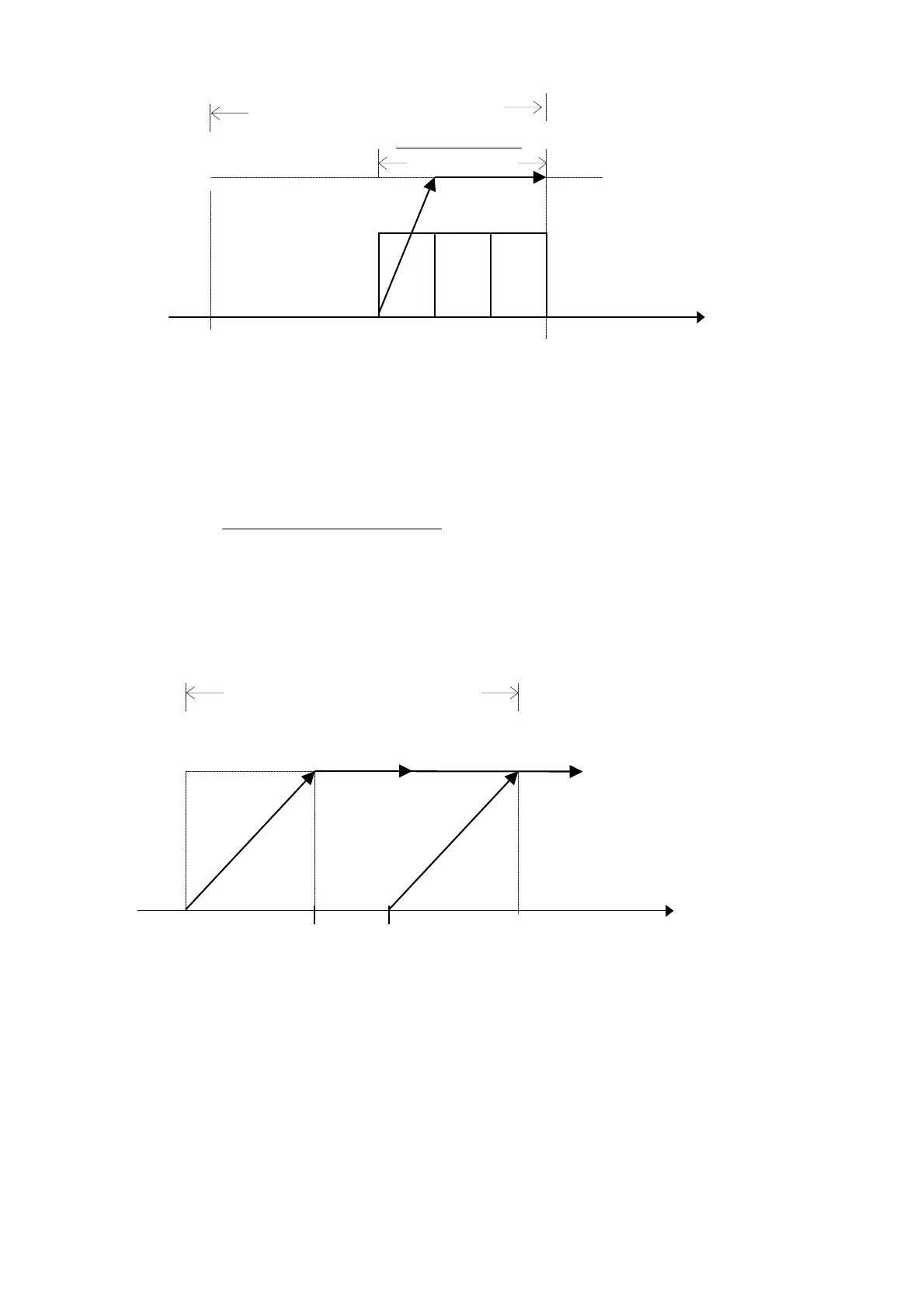
15.8.2 Proportional + integral control
The devices, whether they are valve or fans, will be activated in the second half of the control differential through the effect of the integrating
control. Their activation will be tied to the set integrating constant: the slower it is, the greater the value attributed to the specific parameter.
The proportional control ramp of the Free Cooling valve will be calculated inside the first activation step of the fans. In this way, when the first
fan is enabled, the valve will be completely open, and, therefore, water flow in the Free Cooling exchanger will be at maximum level.
The activation steps of the fans will be positioned proportionally inside the Free Cooling control differential.
To calculate the amplitude of each step, use the following relation:
Step amplitude = Free Cooling Differential
(Number of Master fans X number of cards)
It is assumed that all the circuits controlled by the pCO cards making up the system are equivalent and that the number of controlled devices is
the same.
15.9 0-10 Volt Free Cooling valve with inverter controlled condensation
15.9.1 Proportional control
The control proportional ramp of the Free Cooling valve will be calculated inside the area determined by the thresholds:
Control Set-point -Free Cooling Differential/2
Control Set-point -Free Cooling Differential/2 + valve maximum opening % Threshold
The control proportional ramp of the condensation inverter will be calculated inside the area determined by the thresholds:
Control Set-point -Free Cooling Differential/2 + inverter speed minimum % Threshold
Control Set-point + Free Cooling Differential/2
The start/end points of the two control ramps can be modified at the user's discretion by varying the value of the thresholds (see graph) as a
percentage of the value of the set Free Cooling differential.
For the Free Cooling valve, the setting field ranges from 25 to 100% of the differential.
For the condensation inverter, the setting field ranges from 0 to 75% of the differential.
Free Cooling Set point
V1
V2
V3
0 Volt
10 Volt
Free Cooling 0 to 10 V
Valve
Free Cooling Differential
Evaporator Outlet
Temperature
Free Cooling Differential
2
Evaporator Outlet
valve maximum opening %
threshold
inverter speed minimum
% threshold
Free Cooling Differential
0 Volt
10 Volt
Free Cooling 0 to 10 V
Valve
Inverter Ramp 0 to 10 V
Free Cooling Set point

 Loading...


