Modular Standard HP Chiller for Carel driver
Carel code +030221236- Rel. 1.0 dated 7 July 2003
20
9 CONTROL
9.1 INLET TEMPERATURE CONTROL
9.1.1 INLETS USED
• Inlet temperature
9.1.2 OUTLETS USED
• All compressors and the relevant capacity controls
9.1.3 PARAMETERS USED
• Control set point
• Proportional band for control at inlet.
• Type of control (proportional or proportional + integral)
• Integration time (if the proportional + integral control is enabled)
• Type of unit
• Total number of compressors
• Number of capacity controls
Example: a control diagram for machines with a max. of 2 semi-hermetic compressors with a max. of three capacity controls
All network compressors will be positioned proportionally in the band.
9.2 TEMPERATURE CONTROL AT OUTLETS
9.2.1 INLETS USED
• Outlet temperature
9.2.2 OUTLETS USED
• All compressors and capacity controls
9.2.3 PARAMETERS USED
• Control set point
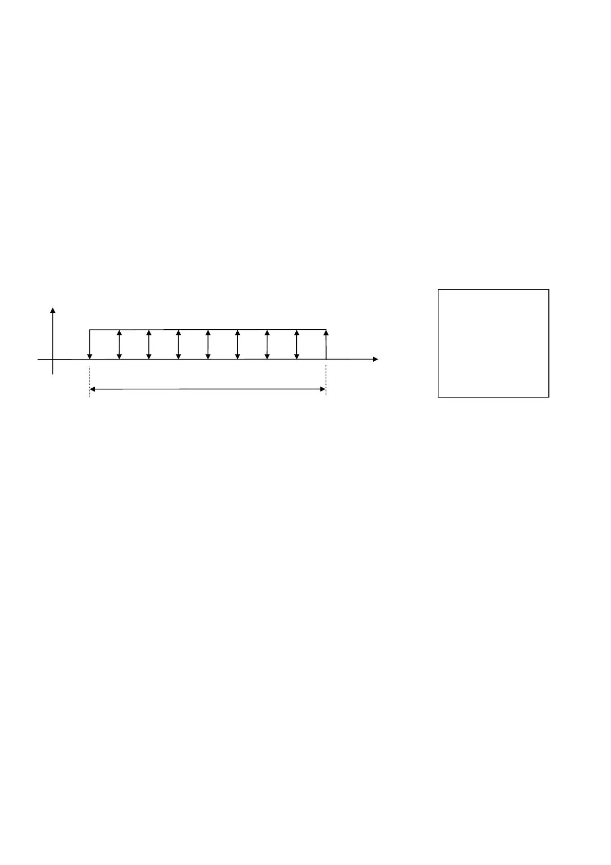
• Neutral band for control. at outlet
• Step activation time
• Step disabling time
• Minimum limit of temperature at outlet (powers down all compressors without observing the disabling time)
• Maximum limit of temperature at outlet (powers down all compressors without observing the disabling time)
set point
Control band
C1 P1 P2 P3 C2 P1 P2 P3
Temperature
°C
C1 % compressor 1
P1 % capacity control 1
P2 % capacity control 2
P3 % capacity control 3
C2 % compressor 2
P1 % capacity control 1
P2 % capacity control 2
P3 % capacity control 3

 Loading...


