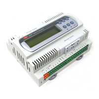
Modular Standard HP Chiller for Carel driver
Carel code +030221236- Rel. 1.0 dated 7 July 2003
23
10.1 DRIVER PARAMETERS
In this section, we shall explain the essential parameters of greatest interest for setting up the driver.
The screen code (see chap. "PARAMETERS LIST") is used (in brackets) to describe these parameters, in order to help you find the appropriate
parameter.
Each pCO* card manages a maximum of two drivers. As they have the same configuration, this section illustrates the first driver's configuration
only.
10.1.1 Valve Type and battery presence (F0)
The type of valve and battery presence are set on this first screen. These are the possible valves:
• Alco (EX5, EX6, EX7, EX8)
• Sporlan (SEI 0.5, SEI 1, SEI 2, SEI 3.5, SEI 6, SEI 8,5, SEH 100, SEH 175, SEH 250)
• Danfoss (ETS50, ETS100)
• Carel EVD200
• Custom valve (if none of the valves described above are the one used by the user).
10.1.2 EEV circ. percentage ratio (F1)
This indicates the ratio, as a percentage, between the maximum refrigerating capacity of the circuit controlled by the EVDriver and the capacity
obtainable through maximum opening of the expansion valve, under the same operating conditions. Operating conditions are all the system
variables which influence the refrigerating yield of both the system and the valve (condensation temperature, subcooling, superheating, loss of
load,….)
10.1.3 Super-heat set-point in mode CH/HP/DF (F4/F5/F6)
Set-point for superheating control. We advise you not to use values below 3°C
Superheating control dead band. Control is not enabled for temperatures in the range Sheat Set – SH Dead band and Sheat Set + SH Dead band
For example, a dead band value of 1°C, with a set-point of 5°C, means that superheating can vary from 4°C and 6°C without the control
attempting to change it. The algorithm resumes controlling outside that range. We advise you not to use values of over 2°C
Attention: Suffix -CH means that these parameters are used for chiller operation. These parameters must be configured also for heat pump and
defrosting operation.
10.1.4 PID parameters in operation CH/HP/DF (F4/F5/F6)
Constants used for PID control of the EVDriver. The respectively represent the following:
• Proportional gain
• Integrating time constant
• Derivative time constant
In this case too, the three types of operation must be configured.
10.1.5 Low super-heat threshold for operation CH/HP/DF (F4/F5/F6)
The low superheating threshold and relevant integral constant for activating the low superheating protection. This protection usually leads to the
closing of the electronic valve.If the integral constant is zero, the protection is disabled.
In this case too, the three types of operation must be configured.
10.1.6 LOP threshold in operation CH/HP/DF (F4/F5/F6)
The low intake pressure threshold and relevant integral constant for activating LOP protection. This protection usually leads to the opening of
the electronic valve. If the integral constant is zero, the protection is disabled.
In this case too, the three types of operation must be configured.
10.1.7 MOP threshold in operation CH/HP/DF (F4/F5/F6)
The high intake pressure threshold and relevant integral constant for activating MOP protection. This protection usually leads to the closing of
the electronic valve. If the integral constant is zero, the protection is disabled.
In this case too, the three types of operation must be configured.
10.1.8 High condensation temperature threshold in operation CH/HP/DF (F4/F5/F6)
The high condensation pressure threshold and relevant integral constant for activating the protection. This protection usually leads to the closing
of the electronic valve. If the integral constant is zero, the protection is disabled.
In this case too, the three types of operation must be configured.
10.1.9 Refrigerant (Fy)
Type of refrigerant used in the unit:
10.1.10 Configuration of the evaporation pressure probe (FE)
This screen is used for setting the minimum and maximum values of the refrigerant pressure probe range at the outlet of the evaporator
connected to the driver.

 Loading...