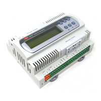
Modular Standard HP Chiller for Carel driver
Carel code +030221236- Rel. 1.0 dated 7 July 2003
38
17 ALARMS
17.1 General description
Alarms are divided into three categories:
• Warning-only alarms (only warning on display and buzzer, warning on display, buzzer, alarm relay)
• Circuit alarms (only disable relevant circuit, warning on display, buzzer, alarm relay)
• Serious alarm (disables whole system, warning on display, buzzer, alarm relay)
17.1.1 WARNING-ONLY ALARMS
• Unit maintenance alarm
• Compressor maintenance alarm
• Clock card faulty or disconnected alarm
• Unit disconnected from network alarm
• Driver alarms: high pressure on driver, superheating and valve not closed last time the unit switched off (“valve not closed during switch-off”)
17.1.2 CIRCUIT ALARMS
• High pressure/pressure switch alarm immediate compressor shut-down, with manual reset
• Low pressure alarm delayed at compressor start, immediate in steady state, with manual reset
• Compressor thermal overload alarm immediate compressor shut-down, with manual reset
• Oil differential alarm delayed on acquisition, with manual reset
• Fan thermal overload alarm immediate fan shut-down, with manual reset
• Driver alarm - probe error shut-down of compressor(s) on relevant circuit
• Driver alarm - motor error shut-down of compressor(s) on relevant circuit
• Driver alarm - EEPROM error shut-down of compressor(s) on relevant circuit
• Driver alarm - battery malfunct. shut-down of compressor(s) on relevant circuit (enablable)
• Driver alarm - low pressure shut-down of compressor(s) on relevant circuit (enablable and delayable)
17.1.3 SERIOUS ALARMS
• no water flow alarm digital input delayed at start and in steady state
• evaporator antifreeze alarm generated by evaporator outlet probe, with set point and differential for reset, reset manually
• serious alarm from digital input immediate unit shut-down, with manual reset
Alarms are reset by pressing the alarm key twice.
None of the driver alarms are serious ones.
17.2 ALARM LOGGING
The alarm log can store the standard chiller’s operating state when alarms are generated or at particular times. Each set of data stored is an event
that can be viewed by selecting it from the list of logged events. The log proves useful when troubleshooting because a “snapshot” is taken of
the system when the alarm occurs, which can later be used to help determine possible causes and how to remedy the trouble.
There are two kinds of log in the program, the STANDARD log and ADVANCED log.
17.2.1 STANDARD LOG
The pCO* boards’ considerable buffer space means events can be saved in the STANDARD log, which is always available on the various
boards. If there is no clock card (optional extra on pCO1 and pCOC, built-in feature on pCO2), the STANDARD log just gives the alarm code.
The maximum number of events that can be logged is 100. Once the hundredth alarm is reached, i.e. the last available slot in the memory is
taken, the oldest alarm (00) is erased as it is overwritten with the next alarm, and so on for subsequent events. Logged events cannot be deleted
by the user unless installing factory settings. The STANDARD log screen can be called up by pressing the MAINTENANCE key, and looks
like this:
+--------------------+
¦Alarms Log A2¦
¦Event number 00¦
¦Alarm Code 000¦
¦Date 00:00 00/00/00¦
+--------------------+
For each alarm, the following data are stored relating to the standard chiller at the time of the alarm:
• alarm code
• time
• date
• chronological event number (0-99)
The chronological event number indicates the “seniority” of the event with respect to the 100 available storage slots. The alarm with number 00
is the first to occur after the STANDARD logs are enabled, and hence the oldest.
If you move the cursor onto the chronological number, you can run through the alarm log, from 0 to 99, using the arrow keys.
For instance, if you are on position 00, pressing the down arrow will not take you anywhere.
If 15 alarms have been logged, for instance, and you are on position 014, pressing the up arrow will not take you anywhere.

 Loading...