Do you have a question about the Carel UE001 and is the answer not in the manual?
| Brand | Carel |
|---|---|
| Model | UE001 |
| Category | Humidifier |
| Language | English |
Covers electrical shock, water leaks, burns, installation, and general usage safety guidelines.
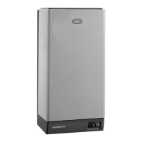
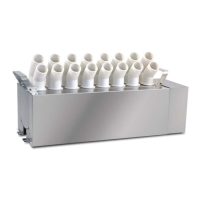
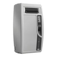
Introduction to the isothermal immersed electrode humidifiers and model identification.
Detailed instructions for connecting the water supply, including valves and filters.
Guidance on connecting the drain line, including traps and slope requirements.
Steps for safely connecting the main power supply cable to the humidifier.
Guide for connecting various control signals like humidistats and remote contacts.
Details on connecting alarm signaling and dehumidification device contacts.
Configuration for sending SMS alerts for alarms and malfunctions.
Checks before starting, initial startup procedure, and stopping the unit.
Setting control type, signal type, measurement units, and cylinder sequence.
Setting minimum, maximum values, and offsets for main and limit probes.
Configuring operating parameters, alarms, and cylinder lifetime settings.
Setting parameters for automatic draining, foam management, and inactivity drains.
Configuring supervisor connection, network settings, and SMS alert setup.
Performing manual tests for functions like contactors, valves, drain pumps, and relays.
Describes common alarms, their meanings, causes, and solutions.
Details on alarm reset, relay activation, consequences, and signal types.
Electrical wiring diagram for single-phase models UE001 to UE009.
Electrical wiring diagram for three-phase models UE003 to UE018.
Electrical wiring diagram for three-phase models UE025 to UE065.
Electrical wiring diagram for three-phase models UE090 to UE130.