140
6.3 — Smart Controller Inputs/Outputs
CONTROLLER INPUT SIGNAL
The smart controller (see Fig. 33) receives a 0 to 10 VDC
input signal from the system’s rack controller. This signal is
inversely proportional to the capacity demand required from
the compressor. A 0 VDC demand signal represents a 100%
capacity output from the compressor. The minimum demand
voltage signal (compressor fully unloaded), depends on the
compressor configuration selected by the smart controller
DIP switches (see Section 6.4).
POWER SUPPLY INPUT
The smart controller requires a 24 VAC (±10%), 50/60 Hz
source to power the module. The maximum continuous rat-
ing is 5 VA. Control power should be isolated with a trans-
former from the main power supply.
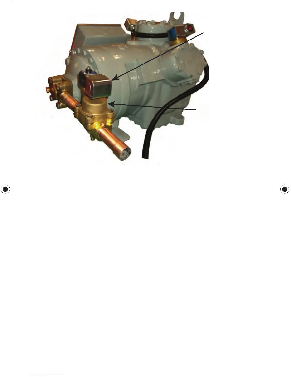
SOLENOID COIL
P/N 8ADB000688
(240 vac)
P/N 8ADB000689
(120 vac)
PWM VALVE
P/N 8ADB000690
and
P/N 8ADB000907
Fig. 32 — PWM Valve Installed