151
6.5 — Service Table
NOTE: Not all smart unloading applications use the smart
controller for discharge temperature control and protection.
The Service and LED tables allow the Installer and/or Ser-
vice Technician the ability to verify the smart controller is
functioning properly once installation is complete and the
refrigeration system is ready for service. Based on the volt-
age input signal to the smart controller, the PWM cycle and
LED status of the smart compressor can be checked per the
tables.
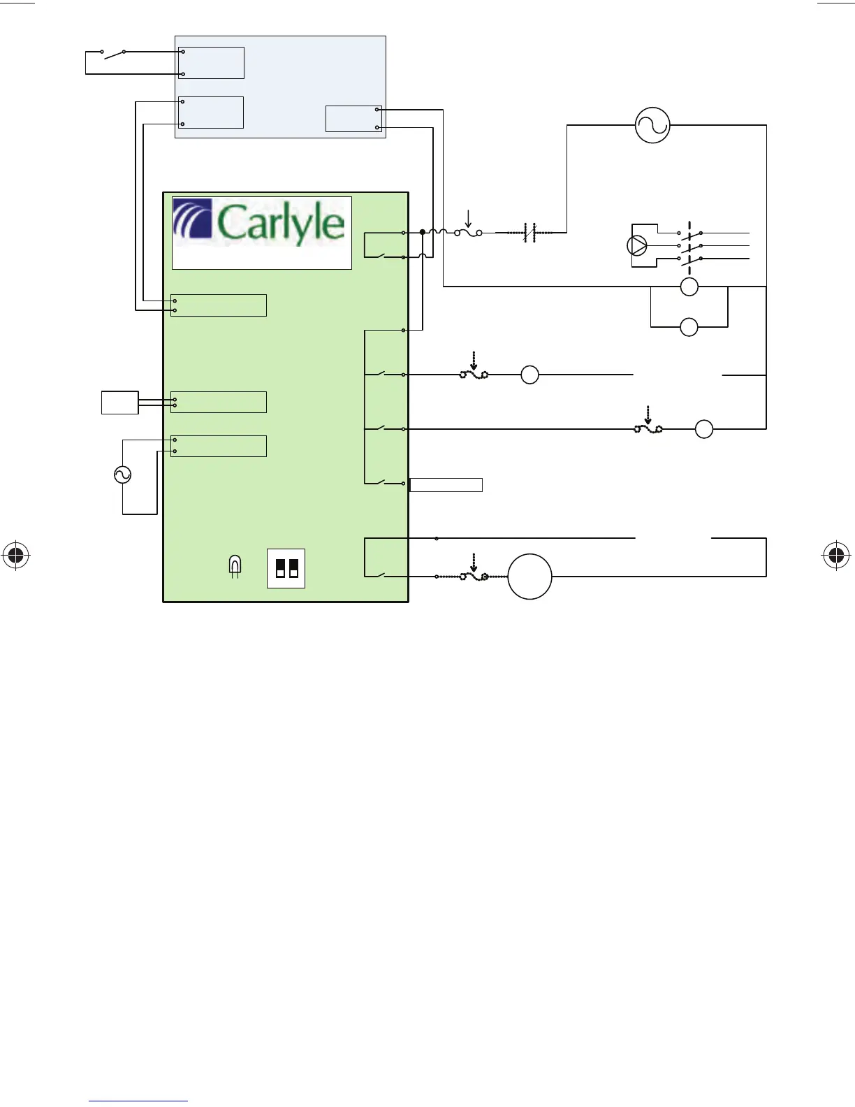
Fig. 37 — Electrical Schematic, Compressors with
1 Unloading Head or PWM Valve
M
Cylinder Head Fan
230 /460 Vac Input
Liquid
Injection
Solenoid
Unloader
Coil 1
SMART Unloading Module
T
discharge
Sensor
PT1000 D ischarge
GN D T em perature
0..10VDC Demand
GN D Signal
24 Vac
Compressor
Motor
24 Vac
Fuse
Compressor
Contactor
Protection D evices
Installed Here
115 /230 Vac Control Pow er
LN
2 am p 120 V
1 am p 240 V
Fuse
(tim e delay )
Alternate
½ amp Fuse
Alternate
½ amp Fuse
Control
Voltage
Comp
Injection
Coil 1
Coil 2
Wire
Leads
AC in
Rack
Controller
Compressor
Alarm Status
Input
Compressor
Capacity
Output (0-10 Vdc)
Compressor
Start/Stop
Isolation Relay
Com pressor Selector
ON
1 2
LED
Indicator
Isolation Relay
120 /208-230 Vac Input
Do not use Coil #2