60
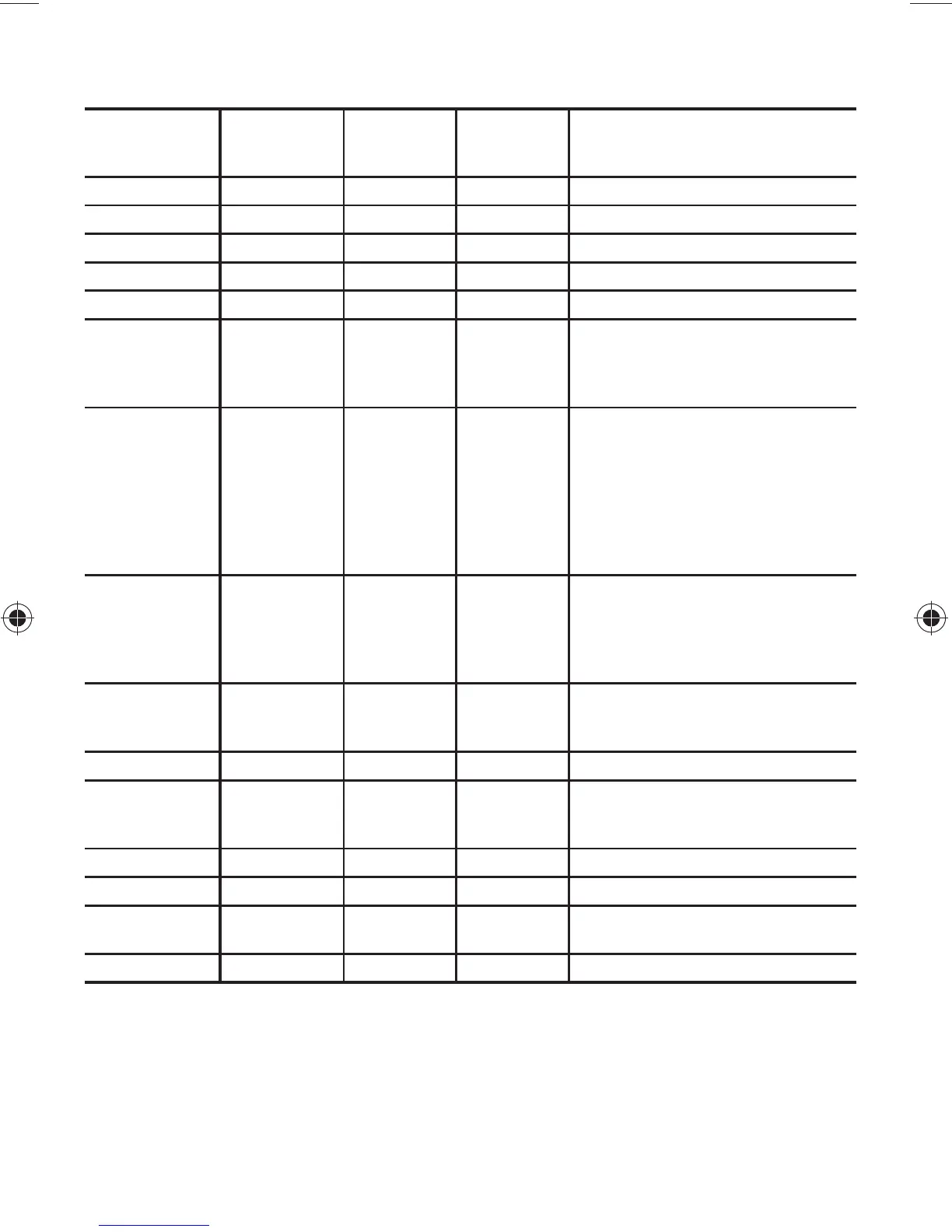
2.10 — Torque Guide - 06D and 06CC (16 to 37 Cfm)
Compressors
LEGEND
(CC) - Compound Cooling compressors only
NM - Newton meter (metric torque rating)
SAE - Society of Automotive Engineers
*See Fig. 30 page 133, for jam locations.
Torque for jam nut #3 for compressors manu-
factured after 0203J--. For compressors built
before this, jumper bar must be under jam nut
#3 or Loctite #089 applied to jam nut #2, or use
12 ft-lb.
NOTE: Bolt sizes and thread pitch: Compres-
sors are built using English unit bolts. The bolts
have no exact metric equivalents. Therefore, to
prevent possible cross-threading, loose bolts, or
damage to threaded portions of the casing,
comparable metric measurements are not
included.
SIZE
DIAMETER
(in.)
THREADS
PER INCH
TORQUE
RANGE
(FT-LB)
TORQUE
RANGE
(NM)
USAGE
1/16 Pipe 8-12 11-16 Pipe plug crankshaft
1/8 Pipe 6-10 8-14 Oil return check valve
No. 10 324-65-8 Oil pump drive segment
1/4 Pipe 20-25 27-34 Pipe plug
1/4 20 10-12 14-16 Con-rod cap screw
1/4 28 12-15 16-20
Baffle plate crankshaft
Side shield
Oil pump drive segment
Unloader
5/16 18
16-20
16-20
16-20
16-20
16-20
16-20
20-25
20-33
22-27
22-27
22-27
22-27
22-27
22-27
27-34
27-44
Cover plate bearing head
Terminal plate cap screw
Interstage outlet (CC)
Interstage manifold (CC)
Liquid injection (CC)
Suction manifold (CC)
Suction service valve
Discharge service valve
3/8 16 30-35 40-48
P.E. bearing head, crankcase
Bottom plate, crankcase
Compressor foot
Cylinder head
Motor end cover, crankcase
3/8 24-SAE 6-12 8-16
P.E. bearing head at
10-o’clock position
NOTE: Not a field usable fitting
7/16 14 55-60 75-81 Motor end cover, crankcase
7/16 20-SAE 6-12 8-16
Oil drain, on bottom cover
plate 4-cyl (18-20 Cfm) and
6-cyl 06D
1/2 20 10-12 14-16 Oil pressure regulator
1/2 1380-90 109-122 Suction service valve
5/8 11 25-30 34-4
0
Equalization spinner tube
assembly
1-1/2 1835-45 48-61 Oil level sight glass
 Loading...


