59
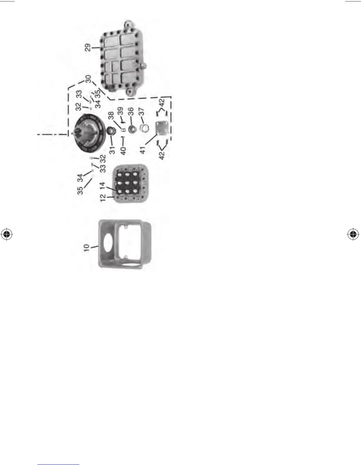
10 — Terminal Box Assembly
12 — Terminal Plate Assembly
14 — Terminal Bolt Assembly
18 — Compressor Crankcase
19 — Motor End Cover
20 — Cylinder Head - Center Bank
21 — Cylinder Head - Side Bank (Unloader
Head Not Shown)
22 — Internal Relief Valve
23 — Crankcase Oil Filter Screen
24 — Oil Sight Glass Assembly
25 — Oil Sight Glass “O” Ring Gasket
26 — Oil Sight Glass Screw
27 — Oil Sight Glass Lock Washer
28 — Pipe Plug Gasket (Hex Head)
29 — Bottom Cover Plate
30 — Pump End Bearing Head Assembly
31 — Pump Rotor
32 — Pump Vane
33 — Pump Vane Spring
34 — Pump Vane Spring Guide
35 — Retaining Spring Guide
36 — Oil Feed Guide Vane
37 — Oil Feed Guide Vane Spring
38 — Oil Pump Drive Segment
39 — Screw, Soc Head 1/4 - 28 x 5/8 in.
40 — Screw, Soc Head #10 - 32 x 1/2 in.
41 — Cover Plate
42 — Cover Plate Cap Screw
43 — Oil Relief Piston
44 — Crankshaft
45 — Bearing Washer
46 — Piston Rings (Oil and Compression)
47 — Piston, Piston Pin and Retaining Ring
Assembly
48 — Connecting Rod and Cap Assembly
49 — Valve Plate Assembly
50 — Valve Plate
51 — Discharge Valve Stop
52 — Discharge Valve
53 — Valve Stop Support
54 — Cap Screw, Valve Stop
55 — Suction Valve (Backers for A/C Mod-
els Not Shown see Fig. 5, page 36)
56 — Check Valve (Use Only with Parallel
Compressor Installations)