154
controller, the PWM valve can easily be controlled to pro-
vide a linear incremental step change to compressor
capacity. The PWM valve is controlled in the same manner
as the unloader head on a compressor, by using a 30-second
PWM control signal from the smart controller (see Func-
tional Overview on page 138).
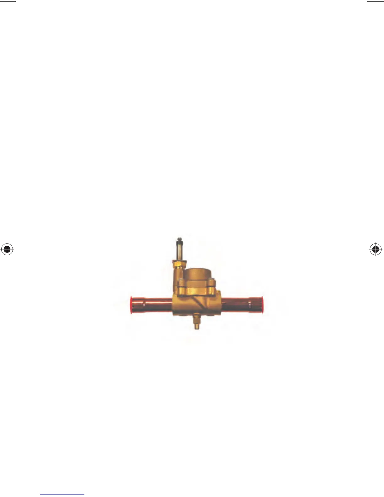
The Carlyle PWM valve (Fig. 39) is designed to work spe-
cifically with the Carlyle 06D, 06CC, and 06M compressor
models for all low, medium, and high temperature applica-
tions.
NOTE: When applying the smart controller with the PWM
valve the standard non-unloading compressor models should
be used and therefore the compressor will not have a “Y” in
the compressor model number. See the PWM Valve Dimen-
sions section for correct usage.
VALVE INSTALLATION AND OPERATION
• Inspect the PWM valve for any shipping damage and
verify the correct part number is called out on the valve.
• The PWM valve installs in the suction line of the com-
pressor. The valve should be installed along a straight
Fig. 39 — PWM Valve PN 8ADB000690 and
8ADB000907