16
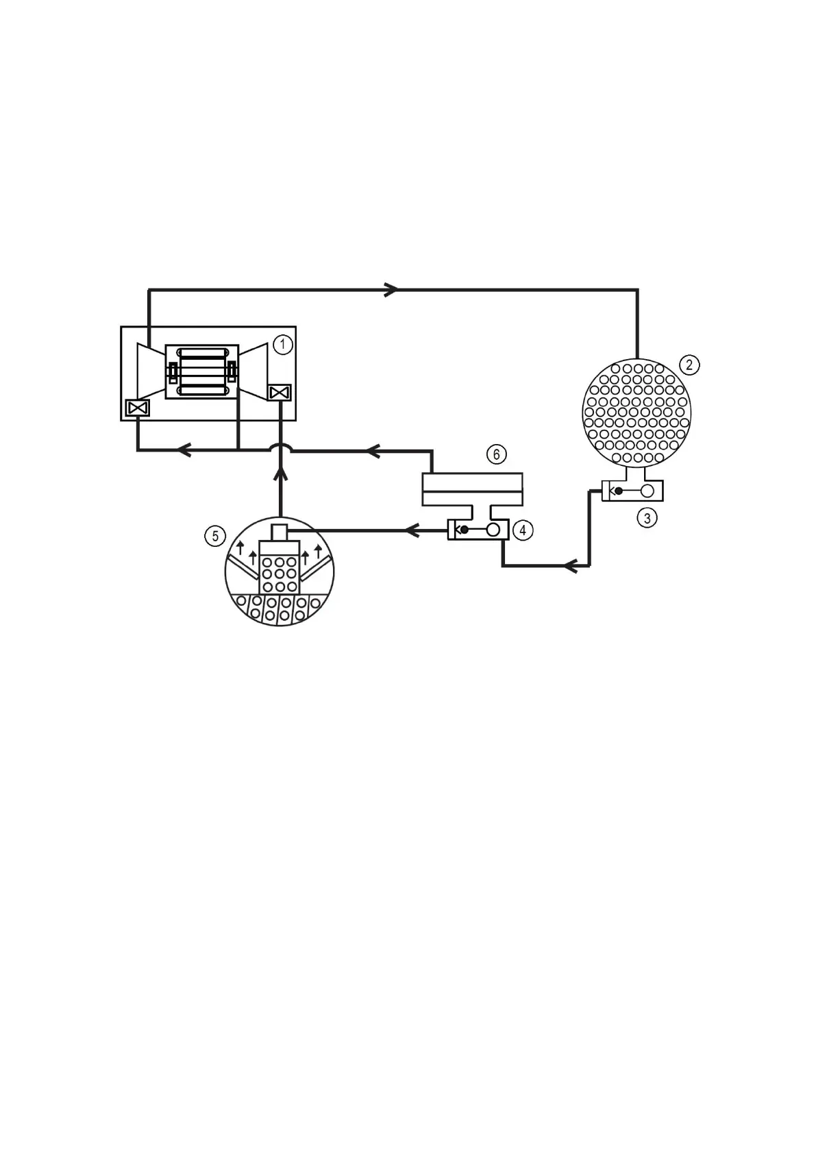
In the economizer, due to lower pressure, as liquid enters the high side chamber, some liquid will flash into a
vapor and cool the remaining liquid. The separated vapor flows to the second stage of the compressor for greater
cycle efficiency. The second stage guide vane on the compressor acts as a pressure regulating device to stabilize
operating conditions. At part load the second stage guide vane will back up gas flow and thereby raises the
economizer pressure to allow appropriate refrigerant flow from economizer to the compressor.
The cooled liquid left in the economizer flows through a low side float valve and then into the evaporator. The float
valve forms a liquid seal to keep vapor from entering the evaporator. The refrigerant is now at a temperature and
pressure at which the cycle began. Fig. 4 summarizes the refrigeration cycle.
The 19DV unit utilizes R-1233zd(E) refrigerant. At atmospheric pressure its boiling point is 18.6°C. The result is
that at normal operating conditions the evaporator typically will be in a vacuum condition and the condenser will
operate at a pressure above atmospheric pressure. Unit near room temperature will be close to atmospheric
pressure.
1.Compressor
2.Condenser
3.High side float chamber
4.Low side float chamber
5.Cooler
6.Economizer
Figure 4 – Refrigeration cycle – 19DV Two Stage Compressor
CAUTION: To avoid adverse effects on chiller operation, considerations must be made to condenser water
temperature control. For steady state operation, the minimum operating refrigerant pressure differential between
cooler and condenser is approximately 7 psid (48 kPa) with a maximum evaporator refrigerant temperature of 18°C.
Consult Chiller Builder for required steady state operational limits and low lift options. Inverted start conditions are
acceptable for short durations of time, but for periods exceeding 5 minutes, a special control solution strategy should
be used to allow the chiller to establish a minimum refrigerant pressure differential (and thereby adequate
equipment cooling).
2.5.5 Refrigerant lubrication cycle
2.5.5.1 Summary
The 19DV Series chiller uses refrigerant to lubricate the bearings. The lubrication control is automatically
controlled by the chiller controls. In normal RUN mode refrigerant is pumped by means of a refrigerant pump from
the high side condenser float chamber to the bearings. Prior to start-up liquid level in the high side condenser float
chamber is maintained by pumping refrigerant liquid from the evaporator to the high side float chamber until level
sensor is satisfied.
If liquid high side float level is not satisfied the pump will move refrigerant from the evaporator to the condenser.
Figures 5 and 6 identify the refrigerant lubrication assembly.

 Loading...


