76
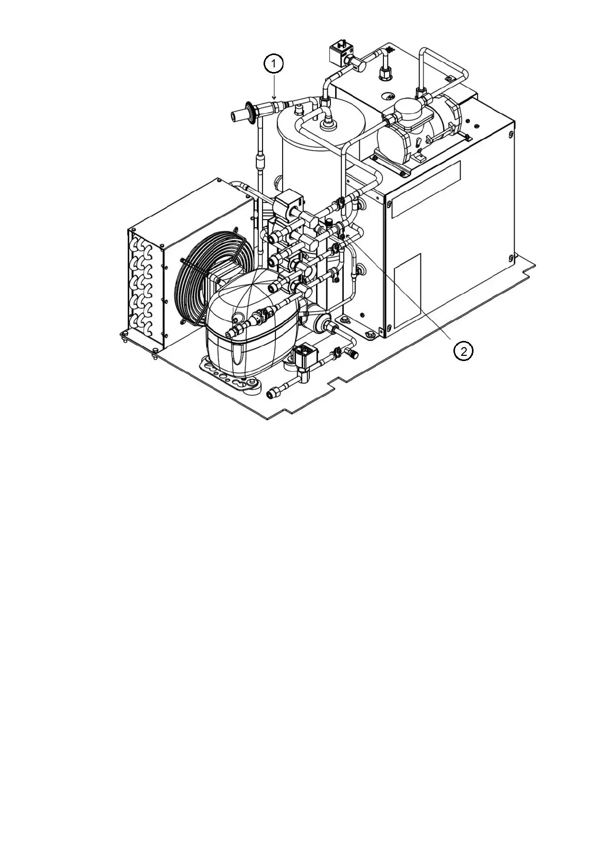
1 : Expansion valve
2 : Suction Schrader valve
Note : Clockwise rotation of expansion valve adjustment screw increases the pressure setting and counterclockwise rotation
decreases pressure setting.
Fig 42 – purge system setting
5.5 Checking the Installation
Use the following instructions to verify the condition of the installation:
1. Turn off, lock out, and tag the input power to the drive.
2. Wait a minimum of 5 minutes for the DC bus to discharge.
3. All wiring should be installed in conformance with the applicable local, national, and international codes.
4. Remove any debris, such as metal shavings from the enclosure.
5. Check that there is adequate clearance around the machine.
6. Verify that the wiring to the terminal strip and the power terminals is correct and that no external voltage
potential are connected to any of the inputs.
7. Verify that all of the VFD power module circuit board connectors are fully engaged and taped in place.
8. Check that the wire size is within terminal specifications and that the wires are tightened properly and
adequately supported.
9. Check that specified branch circuit protection is installed and correctly rated.
10. Check that the incoming power is within ±10% of chiller nameplate voltage.
11. Verify that a properly sized ground wire installed and a suitable earth ground is used. Check for and eliminate
any grounds between the power leads. Verify that all ground leads are unbroken to the power supply. Only a wye
secondary power supply transformer with solidly grounded neutral is acceptable as a power supply to this chiller.
5.6 Check Lubrication Circuit system
Please check condenser float chamber liquid level. If lubrication system works properly, the liquid level sensor
should indicate ON.

 Loading...


