19
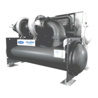
1.Compressor
2.Condenser
3.Motor cooling system
4.Moisture indicator
5.Cooler
Figure 7 – Motor/VFD cooling system
2.5.5.4 VFD cooling
The VFD enclosure is sealed from the atmosphere to protect electronics from outside contaminants. Refrigerant is
routed through a coil in the VFD enclosure to regulate enclosure temperature while still maintaining a temperature
high enough to prevent condensation.
VFD cooling line is branched off the motor cooling supply. The refrigerant is then drained back into the cooler
through the motor/VFD drain line. The power module of the variable-frequency drive is equipped with a heat
exchanger to provide cooling, using the refrigerant in the machine. If equipped with a unit-mounted VFD, the
refrigerant line that feeds the motor cooling also feeds the heat exchanger on the unit-mounted VFD.
2.5.5.5 VFD
All 19DV units are equipped with a VFD to operate the centrifugal hermetic compressor motor. The VFD and
control panel are the main field wiring interfaces for the installing contractor. The VFD and control panel are most
of time mounted on the chiller. See Manufacturer VFD specific information and VFD schematics.
This VFD is used with low voltage motors between 380 and 460 vac. It reduces the starting current inrush by
controlling the voltage and frequency to the compressor motor. Operational parameters and fault codes are
displayed relative to the drive. Refer to specific drive literature along with troubleshooting sections. The display is
also the interface for entering specific chiller operational parameters. These parameters have been
preprogrammed at the factory. VFD is designed to operate in an ambient range of up 40°C.
The compressor power variable-frequency drive cabinet includes the following functional components (identified in
accordance with the references on the wiring diagram):

 Loading...