33
For most applications the refrigerant gas velocity is sufcient
to entrain the liquid refrigerant/oil mixture. Neverthe-less,
table 3 shows the minimum required cooling capacities for
different pipe diameters and different saturated discharge
temperatures.
Table 3 - Minimum capacity (kW) to ensure oil return
for different pipe diameters
30WGA Outside pipe diameter, in
Saturated
condensing
temperature, °C
3/4 7/8 1-1/8 1-3/8 1-5/8 2-1/8 2-5/8
30 3.8 5.6 11.5 19.7 31.0 48.9 86.5
35 3.8 5.7 11.7 19.9 31.5 49.5 87.7
40 3.9 5.8 11.8 20.2 31.9 50.2 88.9
45 3.9 5.9 12.0 20.5 32.3 50.9 90.1
50 4.0 5.9 12.1 20.8 32.7 51.5 91.2
55 4.0 6.0 12.3 21.0 33.1 52.2 92.4
60 4.1 6.1 12.4 21.3 33.5 52.8 93.6
Correction factor, oil entrainment in the discharge lines
Saturated evaporating temperature, °C -7 -1 4 10 16
Correction factor 0.94 0.97 1 1.03 1.06
Table 1 "Discharge line piping" shows the different pipe
diameters based on the unit size and the equivalent circuit
length. These recommended diameters allow oil return within
the application range.
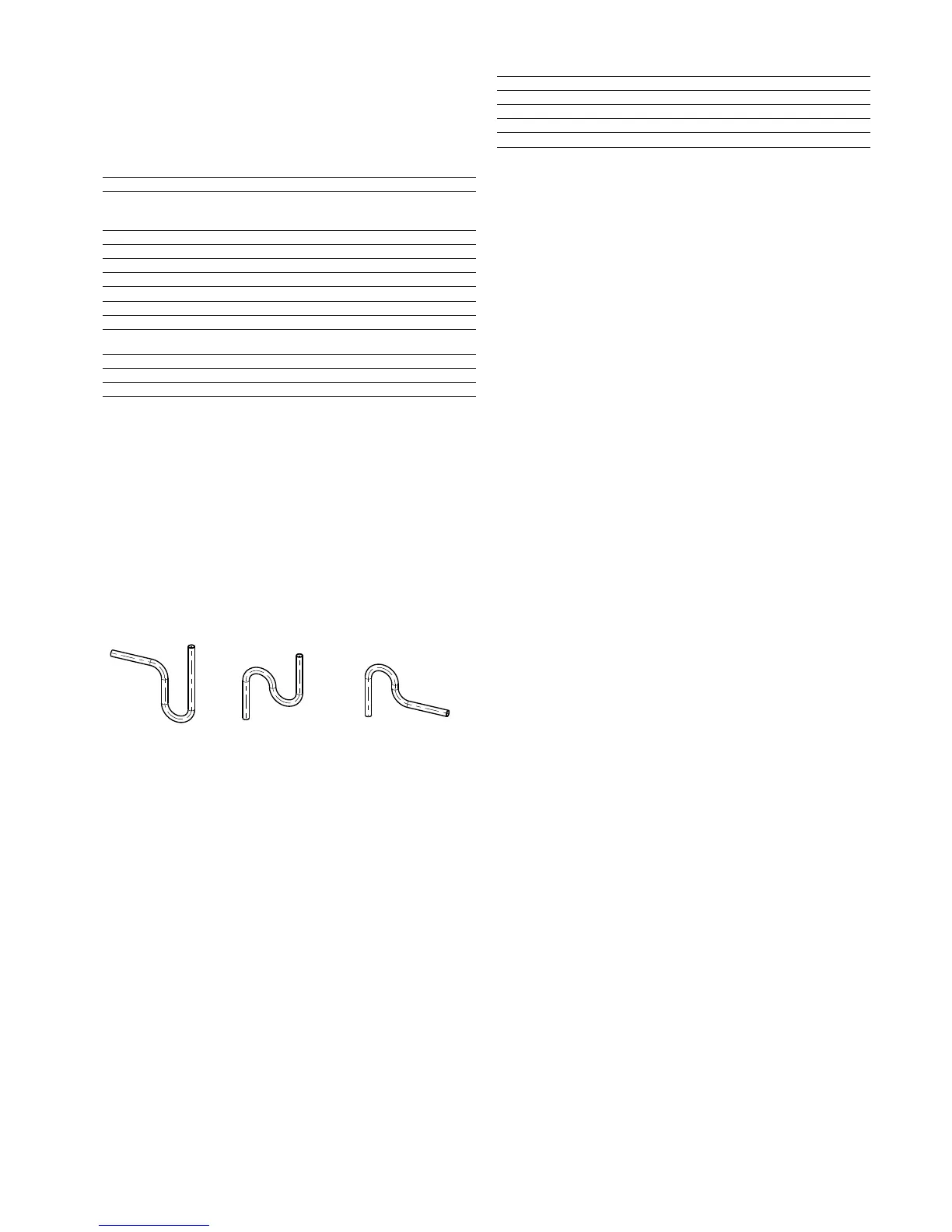
IMPORTANT: Siphon traps must be inserted in the vertical
riser pipes:
• • at the bottom of the piping
• • every 3 m of vertical length
• • at the top of the piping (counter-siphon).
•
Examples
The siphon must be correctly sized to avoid trapping too
much of the liquid oil/refrigérant mixture.
It is advisable to include a slight slope (10 to 20 mm/m) in
the refrigerant ow direction in the horizontal piping between
the 30WGA unit and the condenser.
8.4 - Liquid line sizing
The 30WGA compressors are supplied with an oil that is
fully miscible with refrigerant R-410A in the liquid phase.
Consequently low refrigerant velocities in the liquid lines
are not a problem.
Table 2 “Liquid line piping” shows the different pipe diame-ters
based on the unit size and the equivalent circuit length.
To determine the equivalent liquid line length the lter drier
and the solenoid valve pressure drops must be taken into
consideration. Table 4 below shows the equivalent length for
each unit based on the diameter used.
Bottom of piping Riser pipe Counter-siphon
Table 4 - Equivalent length (m) for lter drier, solenoid
valves, moisture sight-glass (standard supply)
30WGA 020 025 030 035 040 045 050 060 070 080 090
1/2” diameter 4.2 4.2 4.2 4.2 4.2 4.2 2.2 - - - -
5/8'' diameter 12.3 12.3 12.3 12.3 12.3 12.3 5.4 5.4 5.4 5.4 5.4
3/4'' diameter - - - - 29.9 29.9 12.4 12.4 12.4 12.4 12.4
7/8'' diameter - - - - - - - - 25.1 25.1 25.1
The admissible pressure drops in the liquid lines depend
mainly on the subcooling level of the liquid refrigerant at
the condenser outlet. Pressure drops corresponding to 1.5 °C
saturated temperature must not be exceeded.
If the liquid refrigerant head is very high, it may be necessary
to increase the subcooling to prevent a phase change in the
liquid line. A liquid-vapour heat exchanger or an additional
coil can be used for this purpose.
It is advisable to include a slight slope (10 to 20 mm/m) in the
refrigerant ow direction in the horizontal piping between
the remote condenser and the 30WGA unit.
9 - WATER CONNECTIONS
For size and position of the heat exchanger water inlet and
outlet connections refer to the certied dimensional drawings
supplied with the unit. The water pipes must not transmit any
radial or axial force to the heat exchangers nor any vibration.
The water supply must be analysed and appropriate ltering,
treatment, control devices, isolation and bleed valves and
circuits built in, to prevent corrosion, fouling and deterioration
of the pump fittings. Consult either a water treatment
specialist or appropriate literature on the subject.
9.1 - Operating precautions
Design the water circuit with the least number of elbows and
horizontal pipe runs at different levels. The main points to be
checked for the connection are:
• Comply with the water inlet and outlet connections
shown on the unit.
• Install manual or automatic air purge valves at all high
points in the circuit(s).
• Use a pressure reducer to maintain pressure in the
circuit(s) and install a safety valve as well as an expansion
tank. Units with hydronic module and option 293 or
293A include the safety valve and expansion tank.
• Install drain connections at all low points to allow the
whole circuit to be drained.
• Install stop valves, close to the entering and leaving water
connections.
• Use exible connections to reduce vibration transmission.
• If the insulation provided is not sufcient, insulate the
cold-water piping, after testing for leaks, both to reduce
heat loss and to prevent condensation.
• Cover the insulation with a vapour barrier.
• If the external water piping to the unit is in an area where
the ambient temperature can fall below 0 °C, insulate
the piping and install an electric heater on the piping.
NOTE: For units without option 293 or 293A, a screen lter
must be installed as close as possible to the heat exchanger
and in a position that is easily accessible for removal and
cleaning. Units with a hydronic module include this lter.
The mesh size of the lter must be 1.2 mm. If this lter is
 Loading...


