34
dissolved oxygen must be present. Dissolved iron < 5
mg/l with dissolved oxygen < 5 mg/l.
• Dissolved silicon: silicon is an acid element of water and
can also lead to corrosion risks. Content < 1mg/l.
• Water hardness: > 0.5 mmol/l. Values between 1 and 2.5
can be recommended. This will facilitate scale deposit
that can limit corrosion of copper. Values that are too
high can cause piping blockage over time. A total
alkalimetric titre (TAC) below 100 is desirable.
• Dissolved oxygen: Any sudden change in water oxygenation
conditions must be avoided. It is as detrimental to
deoxygenate the water by mixing it with inert gas as it
is to over-oxygenate it by mixing it with pure oxygen.
The disturbance of the oxygenation conditions encourages
destabilisation of copper hydroxides and enlargement
of particles.
• Electric conductivity 10-600µS/cm
• pH: Ideal case pH neutral at 20-25 °C - 7 < pH < 8
If the water circuit must be emptied for longer than one
month, the complete circuit must be placed under nitrogen
charge to avoid any risk of corrosion by differential aeration.
ATTENTION: Filling, completing and draining the water
circuit charge must be done by qualied personnel, using the
air purges and materials that are suitable for the products.
Charging and removing heat exchange uids should be done
with devices that must be included on the water circuit by
the installer. Never use the unit heat exchangers to add heat
exchange uid.
9.2 - Water connections
The diagram below illustrates a typical hydronic installation.
When the hydronic circuit is charged, use the air vents to
evacuate any residual air pockets.
not installed, the plate heat exchanger can quickly become
contaminated at the rst start-up, as it takes on the lter
function, and correct unit operation is affected (reduced
water ow due to increased pressure drop).
Damage due to absence of safety valve, expansion tank or
screen lter (i.e. without option 293 or 293A) is not covered
by the warranty.
Before the system start-up verify that the water circuits are
connected to the appropriate heat exchangers (e.g. no reversal
between evaporator and condenser).
Do not introduce any signicant static or dynamic pressure
into the heat exchange circuit (with regard to the design
operating pressures).
Before any start-up verify that the heat exchange uid is
compatible with the materials and the water circuit coating.
If additives or other uids than those recommended by Carrier
are used, ensure that the uids are not considered as a gas, and
that they belong to class 2, as dened in directive 2014/68/EU.
Carrier recommendations on heat exchange uids:
• No NH
4+
ammonium ions in the water, they are very
detrimental for copper. This is one of the most important
factors for the operating life of copper piping. A content
of several tenths of mg/l will badly corrode the copper
over time (the plate heat exchangers used for these units
have brazed copper joints).
• Cl
-
Chloride ions are detrimental for copper with a risk
of perforations by corrosion by puncture. If possible
keep below 125 mg/l.
• SO
4
2-
sulphate ions can cause perforating corrosion, if
their content is above 30 mg/l.
• No uoride ions (<0.1 mg/l).
• No Fe
2+
and Fe
3+
ions with non negligible levels of
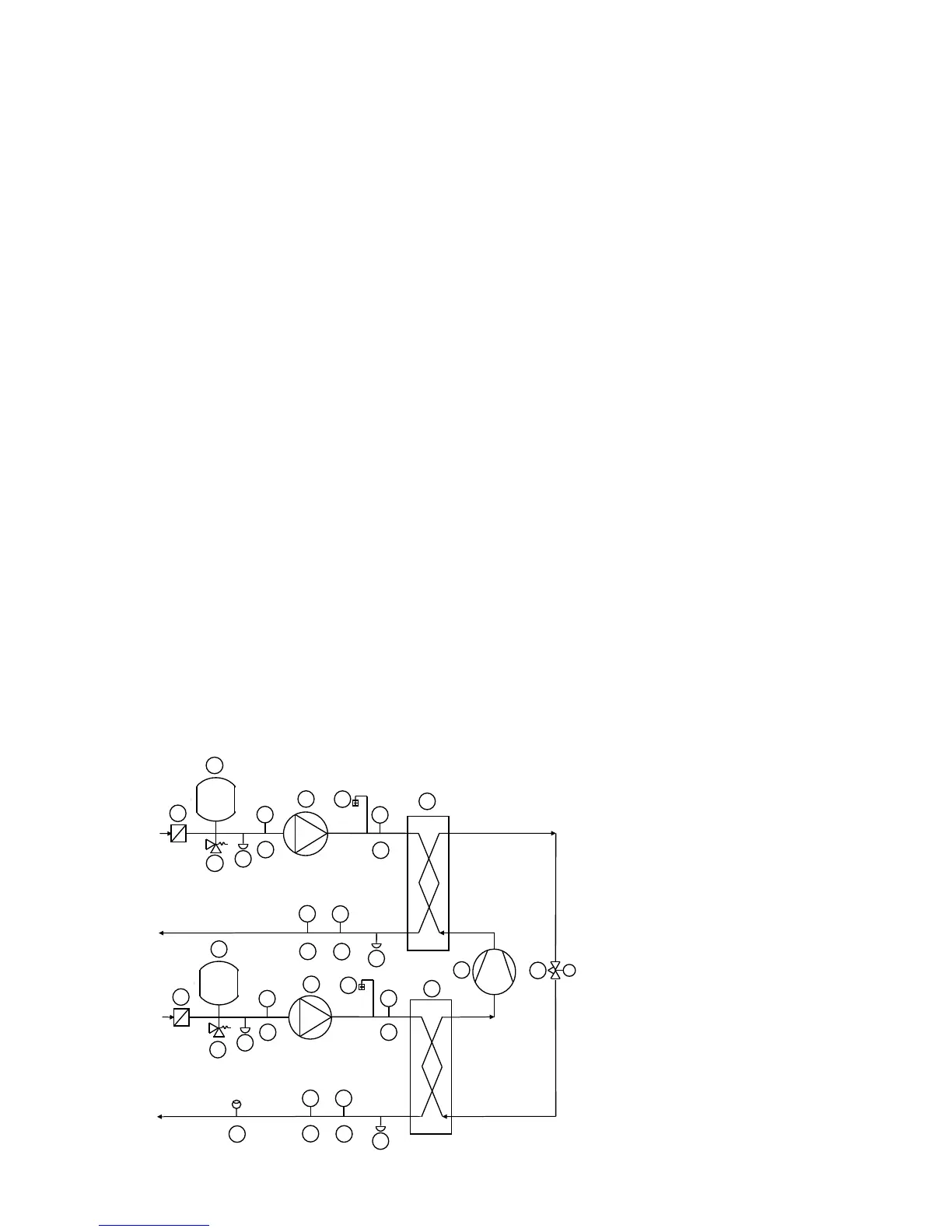
Typical water piping diagram, 61WG/30WG/30WGA units with hydronic modules
Components of unit and hydronic module
1 Victaulicscreenlter(option293or293Aonly)
2 Expansiontank(option293or293Aonly)
3 Safetyvalve(option293or293Aonly)
4 Water pump
5 Air vent
6 Water drain valve
7/8 Entering/leavingpressuresensor
9/10Entering/leavingtemperatureprobe
12 Flow switch 61WG option 272 (sizes 020-045
only)
13 Compressor
14 Evaporator
15 Condenser
16 Expansion device
NOTE: Units without hydronic
module include a ow switch.
2
6
15
10
9
8
5
1
3
4
7
6
14
9
8
5
1
2
4
PT
PT
TT
TT
PT
PT TT
13
16
TT
12
3
7
10
6
6
Unit water inlet
Condenser water loop (61WG/30WG)
Unit water outlet
Unit water inlet
Unit water outlet
Evaporator water loop (61WG/30WG/30WGA)
 Loading...


