System Pilot
Installation and Operation Instructions
Part Number 33PILOT-01
CONTENTS
Page
SAFETY CONSIDERATIONS ...................... 1
GENERAL ........................................ l
INSTALLATION ................................. 1-5
Location ......................................... 1
Power Transformer Wiring ........................ 2
Carrier Network Communication Bus Wiring ..... 2
Mounting ......................................... 2
• RECESS MOUNT
• SURFACE MOUNT
• DECORATIVE BACKPLATE
• SYSTEM PILOT MOUNTING
OPERATION ................................... 6-12
Power-Up Display ................................ 6
OAT Display ...................................... 6
User Interface .................................... 6
Timeout Feature .................................. 8
Program Mode ................................... 8
• ATTACH
• CTLR-[D
• ALARM HIST
• TIME/DATE
• CONFIG. MAINT, SERVICE, SET POINTS,
OR STATUS TABLES
• SCHEDULE
• SETUP
• DETACH
Modifying Set Points ............................ 11
Occupancy Override ............................ 11
Alternate Maintenance Table .................... 11
Bus Scan ........................................ 11
CONFIGURATION TABLES ................... 12-17
Alarm Configuration Table ...................... 12
Broadcast Configuration Table .................. 12
Holiday Configuration Table ..................... 13
Remote Attach Configuration Table ............. 13
System Pilot Configuration Table ................ 15
MAINTENANCE TABLE .......................... 18
System Pilot Maintenance Table ................. 18
SAFETY CONSIDERATIONS
Air-conditioning equipment will provide safe and reliable
service when operated within design specifications. The
equipment should be operated and serviced only by authorized
personnel who have a thorough knowledge of system
operation, safety devices and emergency procedures.
Good judgement should be used in applying any manufac-
turer's instructions to avoid injury to personnel or damage to
equipment and property.
GENERAL
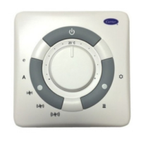
The System Pilot (33PILOT-01) is a component of Canier's
3VTM system and serves as the user-interface and configuration
tool for all Cmrier communicating devices. The System Pilot
can be used to install and commission a 3V zoning system,
linkage compatible air source, univel.sal controllel: and all
other devices operating on the Carrier communicating network.
Additionally, the System Pilot can serve as a wall-mounted
temperature sensor for space temperature measurement. The
occupant can use the System Pilot to change set points and
cause occupancy overrides. A security feature is provided to
limit access of features for unauthorized users.
INSTALLATION
Location -- The System Pilot is the command center for
the 3V control system and is typically located in the main zone
to sense and control telnperature in this zone. The System Pilot
should be located where it is easily accessible and visible to the
end usec
If the System Pilot is being used for system configuration
and diagnostics only (not used as a temperature sensor for the
attached device), then the location of the System Pilot is not
critic_d for accurate temperatme measurement.
For accurate temperature measurement, the following
guidelines should be followed. The System Pilot should be
mounted:
• approximately 5 ft from the floor
• close to or in a frequently used room, preferably on an
inside partitioning wall.
• on a section of wall without pipes or ductwork.
The System Pilot should NOT be mounted:
• close to a window, on an outside wall, or next to a door
leading to the outside
• where exposed to direct light or heat from a lamp, sun,
fireplace, or other temperature-radiating objects which
could cause a false reading
• close to or in direct airflow from supply registers
• in areas with poor air circulation, such as behind a door
or in an alcove.
Any zone may use a System Pilot. The System Pilot
provides a temperature display and buttons to adjust the
desired temperature in that zone only. [t also displays outdoor
temperature received via broadcast on the Carrier Communi-
cating Network.
The System Pilot is approved for indoor use only and
should never be inst_dled with any of its components exposed
to the elements. The System Pilot may be installed in any area
where the temperature remains between 32 to 104 E and the]e
is no condensation.
Manufacturer reserves the right to discontinue, or change at any time, specifications or designs without notice and without incurring obligations.
Book 1 14 PC 111 Catalog No, 533-30013 Printed in U.S.A. Form 33ZC-15SI Pg 1 10-04 Replaces: New
I
Tab 11a 13a