60
Steps Procedure
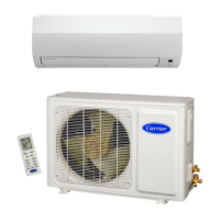
7.
Remove
cabinet
Remove the screws connecting the panel with the
chassis,the motor support and Clapboard Assy then
remove the cabinet.
Remove the grounding wire screw on the control
box assy and then remove the grounding wire.
Disconnect the wiring terminals of reactor,
compressor, high and low pressure switch,
compressor overload protector, temperature sensor,
outdoor fan motor and 4-way valve.
Note: keep pressing the circlip when disconnecting
the wiring terminal of reactor; keep pressing the
retainer when disconnecting other wiring terminals.
Remove the wire inside the wiring groove.
Remove the 2 screws retaining the control box assy
and then lift the control box assy upwards to remove
it.
Remove the nut retaining the fan blade and then
remove the fan blade.
Remove the screws retaining the motor and then
remove the motor.
Remove the screws retaining the motor support and
then remove the motor support.
Remove the 4 screws connecting the reactor and
isolation plate, and then remove the reactor.
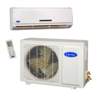
8.Remove control box assy
Motor Support
Reactor
Motor
Control box assy
Cabinet
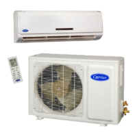
9.Remove fan blade, motor, motor support and reactor
Fan Blade
 Loading...