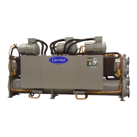
Do you have a question about the Carrier ComfortLink 6 Series and is the answer not in the manual?
| Refrigerant | R-134a |
|---|---|
| Voltage Options | 380V/3Ph/50Hz |
| Control System | ComfortLink controls |
| Dimensions (LxWxH) | Varies by model |
| Weight | Varies by model |
| Sound Pressure Level | 70-85 dB(A) |
Essential safety precautions to be observed during installation, servicing, and operation of the equipment.
Describes the MBB's role in controlling the machine's operation, monitoring inputs, and managing outputs.
Details the SCB module's inputs, outputs, and its role in operating oil heaters, cooler heaters, and oil pumps.
Explains the EXV board's inputs, outputs, and its function in operating electronic expansion devices.
Describes the CCP board's functions for monitoring compressor status, protection, and communication.
Details the EMM's availability and its function in receiving inputs for reset and demand limit.
Explains the function of the 3-position switch for controlling chiller operation.
Describes the function of the emergency on/off switch for immediate shutdown.
Explains the requirements and connections for interfacing with the CCN.
Detailed explanation of the EXV's mechanism, operation, and its role in refrigerant flow control.
Describes how the EXV position is controlled and tracked by the microprocessor.
Explains the function and operation of factory-installed economizers on specific models.
Details how compressor motor winding temperatures are controlled via solenoid valves.
Explains the function of the back pressure valve for ensuring system differential pressure.
Describes the system's use of sensors for controlling chiller operation.
Lists the inputs available for the CCP board, including motor temperature and pressure.
Lists the outputs controlled by the CCP board, such as contactors and solenoids.
Explains how the control system cycles components to maintain setpoint.
Details the display value representing time until unit start.
Procedure for configuring the chiller for minimum load valve control.
Steps to test the operation of the minimum load relay and solenoid valve.
Procedure for adjusting the minimum load ball valve to suit the application.
Describes overrides that modify the normal capacity control routine.
Explains how the control cycles loaders to manage condensing temperature.
Describes the MOP override that reduces capacity based on system pressures.
Overview of microprocessor control for condenser fans to maintain head pressure.
Details head pressure control methods for air-cooled units without Motormaster V.
Details head pressure control methods for air-cooled units with Motormaster V.
Details head pressure control for condenserless units, often applied with 09DK condensers.
Lists field configurable options for head pressure control types and fan staging.
Visual representation of condenser fan locations for 30GX units.
Diagram illustrating head pressure control with the Motormaster V system.
Details various control methods and corresponding cooling set points.
Details fan cycling control via air temperature switches for 09DK044 units.
Describes intermediate-season head pressure control using fan cycling for these units.
Explains how air temperature switches control fans based on temperature.
Details the use of variable speed fan motors for low ambient performance.
Explains how to adjust PID routines for head pressure control.
Describes various methods for controlling the unit's operation.
Explains the different ways to select cooling set points for unit operation.
Details pump control configuration for cooler and condenser systems.
Explains how cooler heaters are energized based on suction and water temperatures.
Details oil heater control based on discharge gas temperature for specific units.
Provides guidance on using the Navigator module for system interface.
Explains the configuration and operation of dual chiller control systems.
Lists available set point modes and their corresponding sub-modes.
Instructions for adjusting the Navigator's contrast settings.
Details the configuration process for a slave chiller in a dual system.
Details on tracking compressor run hours and starts.
Explains temperature reset functionality based on various inputs.
Lists available alarm modes and sub-modes for system monitoring.
Procedure for reading and clearing system alarms and alerts.
Explains how return water temperature affects the cooling set point.
Configuring demand limit using 2-stage switch control.
Configuring demand limit using a 4-20 mA signal input.
Configuring demand limit using CCN loadshed control.
Illustrates the relationship between demand limit signal and capacity.
Diagram illustrating cooling set point based on 4-20 mA signal.
Details menu configuration for 4-20 mA cooling set point control.
Procedure for checking diagnostic information displayed on the Navigator.
Instructions on how to shut off the unit using the Enable/Off/Remote Contact switch.
Lists common causes for complete unit stoppage.
Lists common causes for single circuit stoppage.
Steps required for restarting the unit after a stoppage, depending on the fault.
Explains system alarms and alerts, their causes, and actions taken.
Lists common stoppage faults and their corresponding reset types.
Details specific alarm and alert codes, their causes, and probable causes.
Details the calculation method for oil pressure set point 2.
Procedure for inspecting and opening electronic expansion valves.
Step-by-step procedure for replacing a brazed-plate heat exchanger.
Diagram illustrating the components of a brazed-plate economizer.
Lists torque specifications for EXV components.
Diagram illustrating a typical EXV assembly.
General procedures for servicing cooler and condenser components.
Explains the procedure for plugging leaky tubes in heat exchangers.
Details the process and tools required for retubing heat exchangers.
Lists components used for plugging tubes.
Provides dimensions for tubes related to plugging and rolling.
Procedure for correctly tightening cooler and condenser head bolts.
Guidance on inspecting and cleaning heat exchanger tubes.
Specific instructions for inspecting and cleaning cooler tubes.
Emphasizes the importance of proper water treatment to prevent coil damage.
Details cleaning procedures for condenser coils on 30GXN,R units.
Procedure for cleaning standard, copper, and pre-coated aluminum coils.
Instructions for proper care and cleaning of E-coated aluminum or copper fin coils.
General recommendations for maintaining coil surfaces.
Warning against using harsh chemicals that can damage coils.
Warning against using high velocity water or air for cleaning coils.
Guidance on identifying low refrigerant charge using sight glass and EXV position.
Procedure for adding refrigerant charge to 30HXC systems.
Procedure for adding refrigerant charge to 30GX and 30HXA systems.
Specifies the type of compressor oil required by Carrier.
Lists available oil quantities and their corresponding part numbers.
Details the factory installed oil charges for various unit sizes.
Procedure for adding oil charge to 30HX, GXN, GXR systems.
Diagram illustrating the components of a compressor.
Discusses filter driers and their importance when moisture is detected.
Explains the function of the liquid line service valve for charging and servicing.
Information on thermistor performance verification and replacement.
General locations of thermistor sensors and their terminal connections.
Procedure for replacing thermistors T1, T2, T3, T4, T5, or T6.
Diagram illustrating a filter drier.
Diagram illustrating the process of replacing thermistors.
Data table for motor temperature thermistor resistance values.
Steps for troubleshooting faulty pressure transducers.
Information about the flow sensor, its operation, and troubleshooting nuisance trips.
Diagram showing pressure transducer locations for 2-compressor 30HX units.
Diagram showing pressure transducer locations for 30GXN,R units (top view).
Illustration of the LED display for the chilled water flow switch.
Details on compressor protection features like motor overload and high-pressure switches.
Lists high-pressure switch settings for different unit models.
Explains the operation and de-energization of oil separator heaters.
Details cooler protection mechanisms, including low water temperature.
Discusses relief devices like fusible plugs and pressure relief valves.
Details the function and types of pressure relief valves installed.
Overview of control modules and their diagnostic functions.
Explains the meaning of red LEDs on control modules for status indication.
Explains the meaning of green LEDs on control modules for status indication.
Explains the meaning of the yellow LED on the Main Base Board for CCN communication.
Details CCN interface wiring, cable requirements, and color coding.
Procedure for replacing defective modules and verifying configuration.
Procedure for preparing the chiller for winter shutdown to prevent freeze-up.
General maintenance guidelines and recommended schedules.
Guidelines for routine, monthly, and 3-monthly maintenance tasks.
Procedures for actual unit startup and initial operation.
Steps for performing an actual unit startup under supervision.
Describes the sequence of operations when the chiller starts.
Diagram showing the details of a suction valve.
Diagram illustrating the details of a suction valve handle.
Diagram illustrating power supply wiring connections.
Diagram for remote alarm relay accessory wiring.
Diagram for chilled water pump relay wiring.
Diagram for optional ground fault interrupter wiring.
Diagram for minimum load valve accessory wiring on 30GXN,R units.
Diagram for minimum load valve accessory wiring on 30HX units.
Diagram for condenser pump relay and solenoid valve wiring.
Diagram for chilled water interlock and flow switch input wiring.
Diagram for remote on/off switch input wiring.
Diagram for remote dual setpoint wiring applicable to all units.
Diagram for wiring outdoor-air and space temperature sensors.
Diagram for wiring the Motormaster® option on 30GXN,R units.
Diagram for wiring field-supplied head pressure devices on 30HX units.
Diagram for service port or accessory wiring on 30GX units.
Diagram for wiring the Energy Management Module option.
Table detailing punch-outs and must trip amps for 30GXN,R high ambient models.
Table detailing punch-outs and must trip amps for 30HXC models.
Table detailing punch-outs and must trip amps for 30HXA models.
Example loading sequences for 30HX206 and 30HX271 chillers.
Details the standard loading sequence for 2-compressor units.
Details the close control loading sequence for 3-compressor units.
Details the close control loading sequence for 4-compressor units.
Details the close control loading sequence for 4-compressor units.
Details the close control loading sequence for 4-compressor units.
Lists available accessories for the chillers.
Discusses interfacing chillers with multi-vendor control systems.
Defines objects for system interface across different control systems.
Displays status information for various system options.
Configuration settings for the 7-day occupancy schedule.
Chart showing cooler pressure drop vs flow rate for 30HX units.
Chart showing cooler pressure drop vs flow rate (SI units) for 30HX units.
Chart showing condenser pressure drop vs flow rate (SI units) for 30HX units.
Chart showing cooler pressure drop vs flow rate (SI units) for 30GXN,R080-178.
Chart showing cooler pressure drop vs flow rate for 30GXN,R204-268 units.
Chart showing cooler pressure drop vs flow rate (SI units) for 30GXN,R204-268.
Chart showing cooler pressure drop vs flow rate (SI units) for 30GXN,R281-350.
Chart showing cooler pressure drop for duplex models 30GXN,R328-528.
Chart showing cooler pressure drop vs flow rate (SI units) for duplex models.
Diagram of typical system components for specific models without economizer.
Displays status information for the A_UNIT.
Displays status for Circuit A discrete inputs and outputs.
Displays status for Circuit A analog parameters.
Displays status for Circuit B analog parameters.
Configuration settings for the 7-day occupancy schedule.
Displays maintenance information for current operating modes.
Configuration settings for occupancy parameters.
Configuration options related to chiller operation.
Configuration for schedules and timed overrides.
Configuration settings for the base unit.
Configuration settings related to service parameters.
Maintenance display showing current operating modes.
Maintenance display for load factor information.
Maintenance display for miscellaneous data.
Maintenance display for occupancy settings.
Maintenance display for start counts.
Maintenance display for run hours.
Maintenance display showing software versions.
Maintenance display for WSM (Water System Manager) functions.
Table detailing duplex combinations for 30GXN,R units.
Details the configuration settings for the Motormaster V.
Explains the process of drive programming and parameter access.
Procedures for entering passwords and changing program values.
Procedure for resetting the drive to factory default settings.
Tables outlining program parameters for different operating modes.
Guidance on troubleshooting the Motormaster V control system.
Cross-references controller variables for signal interpretation.
Explains status indications and their meanings.
A log for recording maintenance data for screw liquid chillers.
Section for recording project details.
Section for recording design parameters like capacity and flow rate.
Information regarding chiller model, serial, and compressor details.
Checks related to the chilled water system components and piping.
Checks for the remote condenser system on 30HXA units.
Steps for performing the unit's initial start-up procedure.
Procedure to verify cooler flow rate against specified values.
Instructions for starting the machine and completing operational checks.
Section for recording additional refrigerant charge required.
Section for recording additional oil charge required.
Mode for displaying software versions.
Section for recording configuration information.
Mode for accessing configuration settings.
Sub-mode for display settings.
Sub-mode for base unit configuration.
Sub-mode for option settings 1.
Continuation of configuration settings.
Sub-mode for option settings 2.
Sub-mode for reset configuration.
Sub-mode for setpoint selection.
Continuation of configuration settings.
Sub-mode for service configuration.
Mode for setpoint configuration.
Setpoint configuration for cooling.
Setpoint configuration for heating.
Setpoint configuration for head pressure.
Mode for performing service tests on components.
Sub-mode within Service Test for enabling tests.
Sub-mode within Service Test for testing outputs.
Sub-mode within Service Test for testing compressors.
Details for recording condenser fan motor current.





 Loading...