Communications wiring
Fan Coil CARRIER CORPORATION ©2020
Integration Guide All rights reserved
13
Johnson N2
To set up the Fan Coil for N2
1 Turn off the power for the Fan Coil by disconnecting power terminals.
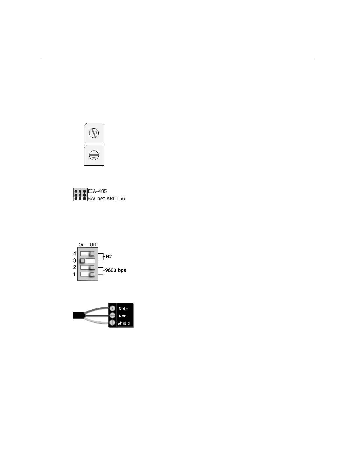
2 Using the rotary switches, set a unique address. Set the Tens (10's) switch to the tens digit of the address,
and set the Ones (1's) switch to the ones digit.
EXAMPLE If the controller’s address is 25, point the arrow on the Tens (10's) switch to 2 and the arrow on
the Ones (1's) switch to 5.
3 Set communications selector for EIA-485.
4 Set both DIP switches 1 and 2 OFF for 9600 bps.
NOTE Use the same baud rate for all devices on the network segment.
5 Set the DIP switches 3 ON and 4 OFF for N2.
The following example is set for 9600 bps and N2.
6 Connect the communications wiring to the Comm port in the screw terminals labeled Net +, Net -, and Shield.
Wire specifications
○ A dedicated 22 AWG shielded twisted pair wire (EIA 485)
○ Maximum wire length 2000 feet (610 meters) or 32 nodes
○ Devices should be daisy-chained and not star-wired
○ Attach the drain/shield wire to both ends of the network segment and through every controller
NOTE Use the same polarity throughout the network segment.
7 Turn on the power for the Fan Coil by connecting power terminals.

 Loading...