EasyManua.ls Logo

Carrier Fan Coil - Wiring Inputs and Outputs

Carrier Fan Coil
50 pages
To Next Page IconTo Next Page
To Previous Page IconTo Previous Page
Loading...
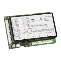
Wiring inputs and outputs
Fan Coil CARRIER CORPORATION ©2020
Integration Guide All rights reserved
3
I/O
Type
I/O
Terminal
Gnd
Terminal
Point Name/
Function
Hardware/
Signal
Zone Temp/
Zone Temp
AI
Rnet
Gnd
Space Temperature - Prime Variable
Communicating
CO
2
or RH
Sensor
AI
IN-1*
2 - Gnd
Optional IAQ or RH sensor
0-5 Vdc
SAT Sensor
AI
IN-2
4 - Gnd
Supply Air Temperature
10K Thermistor
RAT Sensor
AI
IN-3
6 - Gnd
Return Air Temperature
10K Thermistor
Changeover
Temp
AI
IN-4*
8 - Gnd
Changeover switch
Changeover sensor
Dry Contact
Thermistor
Input Channel
#5
BI
IN-5*
1 - Gnd
Remote Occupancy Contact
Fan Status
Dry Contact
Overflow
Contact
BI
IN-6
1 - Gnd
Condensate Overflow Switch
Dry Contact
OA Damper
AO
AO-1*
2 - Gnd
Outdoor Air Damper
0-10 Vdc
2-10 Vdc
2-Pipe Valve /
Heating Valve
AO
AO-2
4 - Gnd
2-Pipe Valve/Heating Coil Valve
0-10 Vdc
Cooling Valve
AO
AO-3
6 - Gnd
Cooling Valve
0-10 Vdc
Fan High Spd
BO
BO-1*
1 - Pwr
High Speed Fan
Stage 2 EH
Relay
Fan Med Spd
BO
BO-2*
1 - Pwr
Medium Speed Fan
Stage 3 EH
Relay
Fan G / Low Spd
BO
BO-3
1 - Pwr
Low Speed Fan
Relay
2-Pos Valve/
Heating Valve
BO
BO-4*
1 - Pwr
2-Pipe Valve
Heating Valve (4-pipe)
EH stage 1 (4-pipe)
Relay
Cooling Valve
BO
BO-5*
1 - Pwr
Cooling Valve (4-pipe)
EH stage 1 (w/2-Pipe/Electric Heat)
DX stage 1
Relay
Legend
AI - Analog Input
BI - Binary Input
AO - Analog Output
BO - Binary Output
*These channels are configurable.
NOTE Connect ZS or SPT sensor to the Rnet port.
Wiring inputs and outputs

Table of Contents

Related product manuals