Figure 174 RTC Battery Orientation
7. Using a suitable tool remove and replace the battery, ensuring that the new cell is latched firmly in
position.
8. Re-attach the casing(s), taking care not to over tighten the fixing screws and reconnect the 24V
power connections FOLLOWED by the Modbus connector.
9. Set the correct time and date via the Time / Date Screen, see Figure 38 and Figure 39.
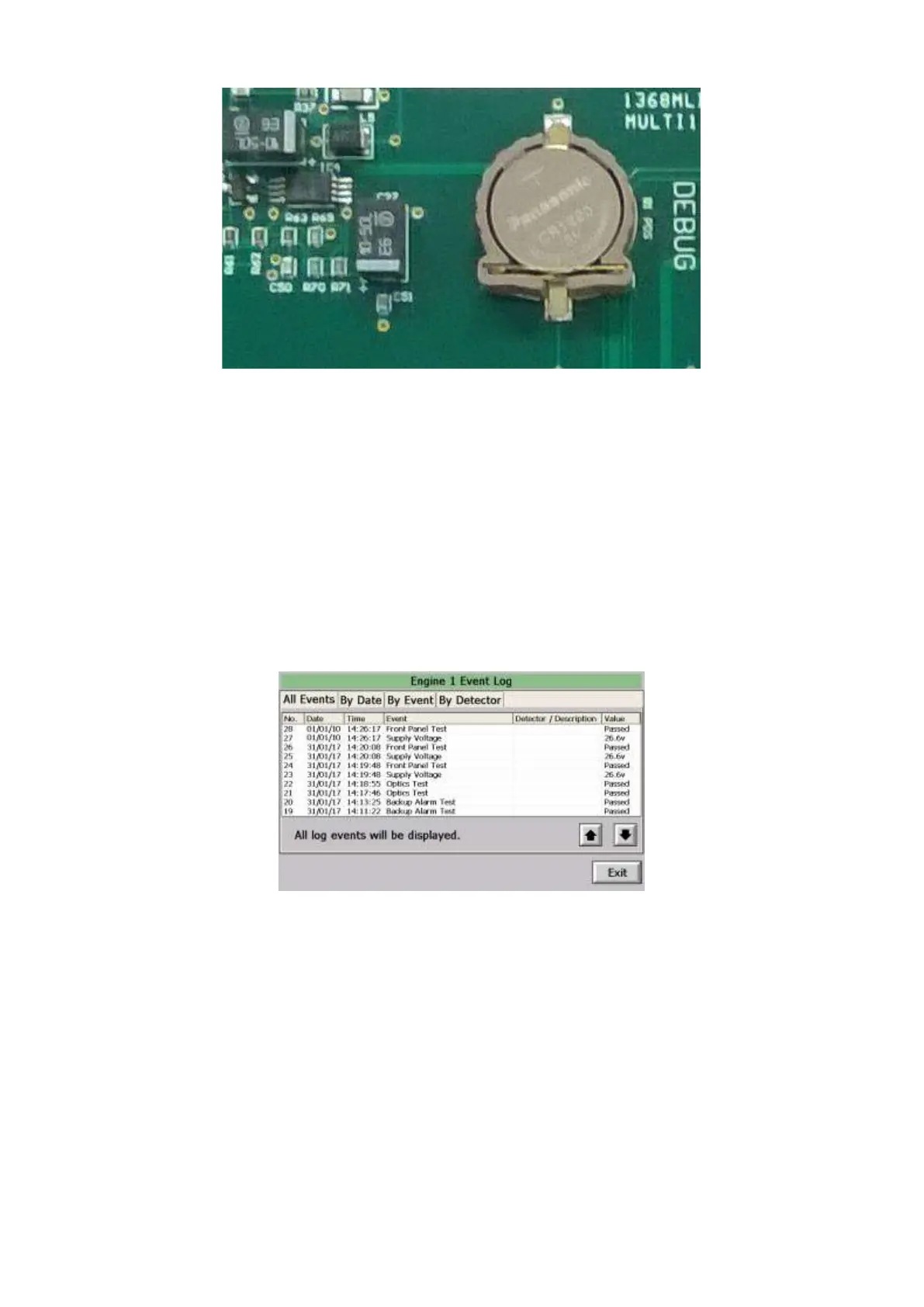
5.2.13 Control Unit Time and Date Incorrect.
When viewing a Control Unit Event Log each event is time stamped with the time and date the event
occurred. The time and date are obtained from the Control Unit real time clock. If the battery used to
maintain the real time clock reaches its end of life, the correct time and date are no longer maintained,
and the time and date shown in the event log will be incorrect. A typical event log is shown below.
Figure 175 Control Unit RTC Battery Failure
Note that the date has changed to 01/01/10.
Note: To maintain the warranty for the Control Unit changing of the battery should be performed
by an approved Service Engineer.
The Control Unit uses a standard CR1220 3v Lithium Coin Battery (12.5mm diameter) see Figure 172.
To ensure reliability and battery life we recommend the use of a quality brand.
To replace the battery:
1. Follow the procedure to replace the Control Unit PCB, see section 6.1.1.
2. Remove the two middle screws fixing the metal can over the PCB.
 Loading...
