62-11863 5-12
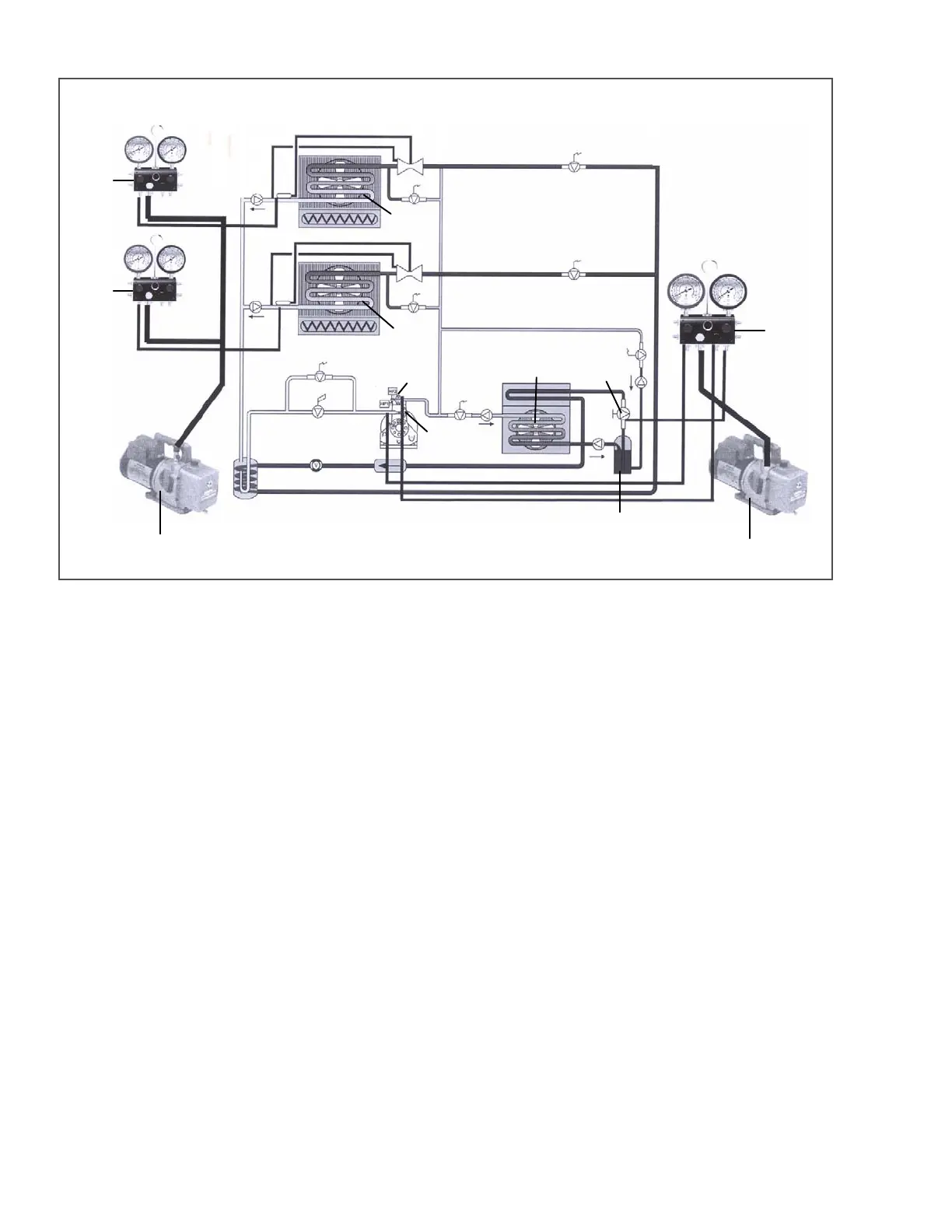
Figure 5.7 Dual Vacuum Pump Connections
[
1. Evaporator Coil
2. Condenser Coil
3. Receiver
4. King Valve
5. Discharge Service Valve
6. Suction Service Valve
7. Evacuation Manifold
8. Vacuum Pump
9. Vacuum Meter
- - - - -
5.7 CHARGING THE REFRIGERANT SYSTEM
5.7.1 Installing a Complete Charge
a. Dehydrate unit and leave in deep vacuum (refer to Section 5.6).
b. Place refrigerant cylinder on scale and connect charging line from cylinder to receiver outlet (king) valve.
Purge charging line at outlet valve.
c. Note weight of refrigerant cylinder.
d. Open liquid valve on refrigerant cylinder. Open king valve halfway and allow the liquid refrigerant to flow into
the unit until the correct weight of refrigerant has been added as indicated by scales. See the following sec-
tion for checking refrigerant charge. Correct charge data is found in Table 2–2.
It is possible that all liquid may not be pulled into the receiver, as outlined in step d.
e. When refrigerant cylinder weight (scale) indicates that the correct charge has been added, close liquid line
valve on cylinder and backseat the king valve.
5.7.2 Checking the Refrigerant Charge
Start unit in COOLING mode and run for approximately ten minutes. Partially block off air flow to condenser coil so
discharge pressure rises to 210 psig (14.8 kg/cm). The unit is correctly charged when the lower receiver sight glass
is full and no refrigerant is in the upper receiver sight glass.

 Loading...


