5-17 62-11863
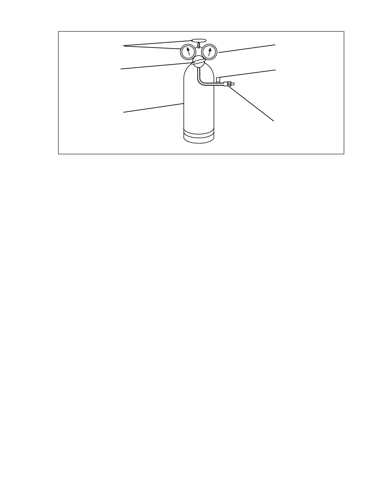
Figure 5.10 Typical Setup for Testing High Pressure Switch
1. Cylinder valve and gauge
2. Pressure regulator
3. Nitrogen cylinder
4. Pressure gauge (0 to 500 psig = 0 to 227 kg/cm
2
5. Bleed-Off valve
6. 1/4 inch connection
- - - - -
a. Remove switch as outlined in
Section 5.12.1
.
b. Connect ohmmeter or continuity light across switch terminals. Ohmmeter will indicate resistance and continuity
light will be lit if switch closes after relieving pressure.
c. Connect switch to a cylinder of dry nitrogen (see
Figure 5.10
).
d. Set nitrogen pressure regulator higher than cutout point on switch being tested. Pressure switch cutout and cut-
in points are shown in
Section 2.7.5
.
e. Close valve on cylinder and open bleed-off valve.
f. Open cylinder valve. Slowly close bleed-off valve and increase pressure until the switch opens. If light is used,
light will go out and if an ohmmeter is used, the meter will indicate open. Note the regulator pressure gauge
reading, which should agree with the cutout pressure as specified in
Section 2.7.5
.
g. Open pressure on gauge. Slowly open bleed-off valve (to decrease pressure) until switch closes (light will light
or ohmmeter will move). Note the regulator pressure gauge reading, which should agree with the cut-in pres-
sure as specified in
Section 2.7.5
.
h. Install new cutout switch after verifying switch settings (refer to
Section 5.6.3
).
i. Evacuate and dehydrate the compressor (refer to
Section 5.6.3
).
5.13 REPLACING RECEIVER SIGHT GLASS ASSEMBLY
There are two types of receiver sight glasses; the floating ball type and the prism type. They are inter-
changeable.
a. Store the refrigerant in an evacuated container (refer to Section 5.6).
b. Unscrew the sight glass assembly. Spread sealing compound on pipe threads of new sight glass assembly
and install.
c. Leak-check receiver sight glass per
Section 5.5
.
d. After leak checking unit, evacuate and dehydrate as outlined in Section 5.6.
e. Add refrigerant charge (refer to Section 5.7.2).
f. Check for noncondensibles.

 Loading...


