62-11863 5-16
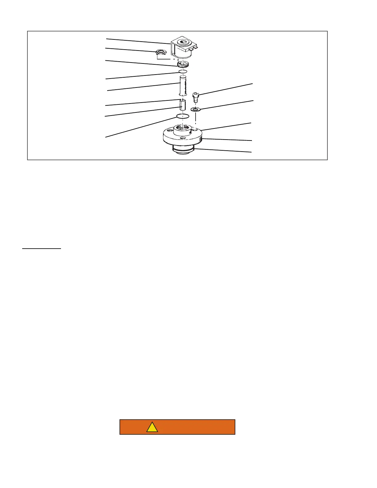
Figure 5.9 Unloader Solenoid Valve
1. Coil Assembly
2. Installation/removal tool
3. Enclosing tube Collar
4. O-ring
5. Enclosing tube
6. Plunger spring
7. Plunger assembly
8. Gasket
9. Valve body
10. Gasket
11. Bolt
12. Gasket, bolt
13. Piston ring
- - - - -
5.11 CHECKING AND REPLACING FILTER DRIER
Two Methods
:
To Check Filter Drier
Check for a restricted or plugged filter drier by feeling the liquid line inlet and outlet connections of the drier car-
tridge. If the outlet side feels cooler than the inlet side, then the filter drier should be changed.
To Replace Filter Drier
a. Pump down the unit per Section 5.4.
b. Remove bracket, then replace drier.
c. Check refrigerant level (refer to Section 5.7.2).
5.12 CHECKING AND REPLACING HIGH PRESSURE CUTOUT SWITCHES (HP1 OR HP2)
5.12.1 Removing High Pressure Switch
The High Pressure switch is located near the top of the compressor.
a. Pump down the unit (refer to Section 5.4). Frontseat both suction and discharge service valves to isolate
compressor (HP) or discharge and receiver valve.
b. Slowly release compressor pressure through the service valve gauge ports.
c. Disconnect wiring and remove.
5.12.2 Checking High Pressure Switch
Do not use a nitrogen cylinder without a pressure regulator. Cylinder pressure is approxi-
mately 2350 psig (159.9 bar). Do not use oxygen in or near a refrigerant system as an explosion
may occur. (See Figure 5.10)

 Loading...


